Elecraft KNB2 Manual User Manual
Page 4
4
Install resistor networks RP1 and RP2. These networks are symmetrical and can be installed in either
of two orientations. Note: Don’t confuse RP1 with connector P1, which also has 8 pins.
i
Before handling U3, touch an unpainted, grounded surface. This is a CMOS IC that can be
damaged by static discharge.
Install 8-pin ICs U1 and U3. Be sure to align the notched or dotted end of each IC with the notched
end of its PC board outline. The labels on the PC board correspond to the labels on the ICs.
Note: Sockets are not supplied and are not needed for these ICs.
Install voltage regulator U2. This device has a plastic body similar to a transistor.
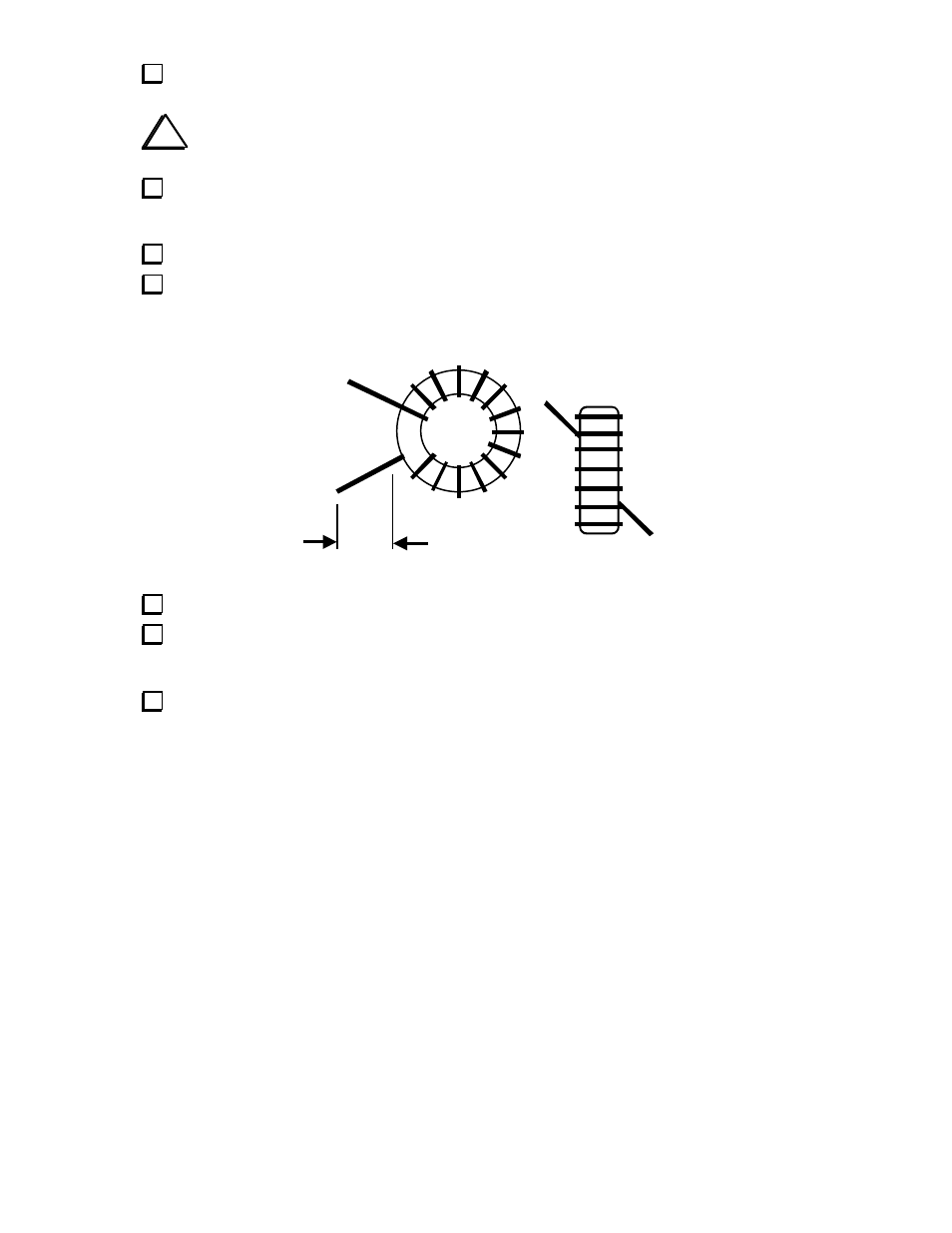
Inductor L1 is wound on a T37-2 core (red) using 12 inches (30 cm) of #26 enamel wire. To wind the
inductor, “sew” the long end of the wire through the core exactly 16 times. Each pass through the core
counts as one turn. The winding should look like the illustration below, except it will have 16 turns.
Remove insulation
Spread out the turns of L1 so they occupy about 85% of the core’s circumference as shown.
Cut L1's leads to about 1/2" (12 mm) long. Completely remove the enamel insulation from the leads
to within 1/8” (3 mm) of the core. You can use a "blob" of solder, a solder pot, butane lighter, or sand-
paper to remove the insulation. If you scrape the insulation off, be careful not to nick the wire.
Install L1 vertically on the PC board as shown by its component outline, then pull the leads taut on
the bottom of the board. Make sure that the exposed part of each lead is shiny and has no insulation.