Figure a-6: routing cables—breakout board, Figure a-7: prop air—wiring – Dynojet 248x: DynoWare EX+ Upgrade User Manual
Page 21
P R O P O R T I O N A L A I R B R A K E I N S T A L L A T I O N
Installation
Version 2
DynoWare EX+ Upgrade For The Model 248 Dynamometer
A-7
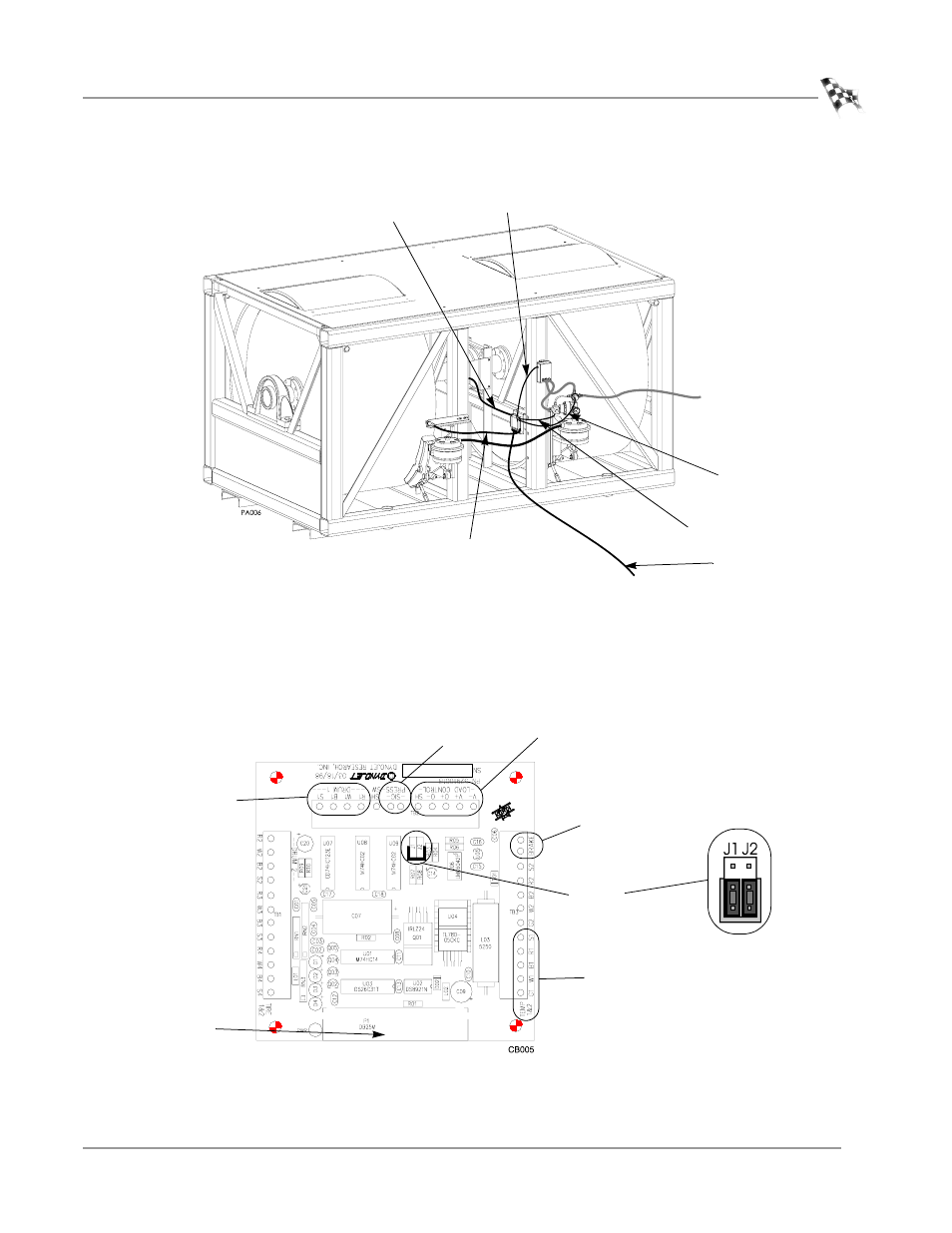
Figure A-6: Routing Cables—Breakout Board
6
The Breakout board jumper settings are preset, however, verify jumpers J1 and J2
are set for the proportional air brake as shown in Figure A-7.
7
Plug the 25 pin DynoWare cable into the bottom of the Breakout board and
tighten the thumb screws.
8
Continue with “Wiring the DynoWare EX+ Modules” on page 8.
Figure A-7: Prop Air—Wiring
EPR cable
data acquisition
cable
brake solenoid
wires
air pressure
switch wire
DynoWare cable
temperature
sensor cable
drum 1
press
load control
brake
temp
DynoWare
cable
jumpers
J1 and J2
proportional air
jumper settings
This manual is related to the following products: