Figure a-5: routing cables—air lines – Dynojet 248x: DynoWare EX+ Upgrade User Manual
Page 19
P R O P O R T I O N A L A I R B R A K E I N S T A L L A T I O N
Installation
Version 2
DynoWare EX+ Upgrade For The Model 248 Dynamometer
A-5
5
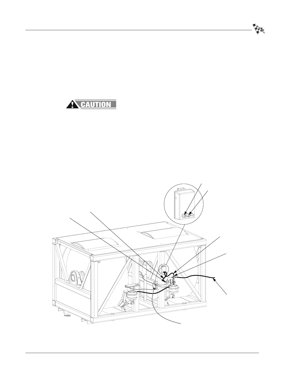
Attach the air line labeled OUT from the EPR to the three-way valve on the prop
air regulator assembly. Push the hose in and hand tighten the fitting.
6
Attach the air line labeled IN from the EPR to the brass four-way fitting on the
prop air regulator assembly.
Note: Pull on both hoses to ensure they are secure. If there is movement, tighten
the fitting.
7
Connect your shop air to the dyno.
Dynojet recommends using an air filter/dryer. Failure to use clean, dry air will
compromise the integrity and life of the air components.
7a
Mount the air pressure regulator on the wall in the shop with the bracket
provided.
7b
Connect a supply air hose to the inlet of the regulator from your shop air
supply and a 3/8" air hose to the outlet side. The regulator should be set to
60 psi.
7c
Connect the 3/8" air hose coming from the air pressure regulator to the
barbed inlet fitting on the prop air regulator assembly
Note: Make sure the arrow on the regulator is the same as the direction of the air
flow.
Figure A-5: Routing Cables—Air Lines
EPR air line in
EPR air line out
regulated air
out
in
three-way valve
brass four-way
fitting