Figure 7: standard air—wiring – Dynojet 248x: DynoWare EX+ Upgrade User Manual
Page 13
D Y N O W A R E E X + U P G R A D E
The DynoWare EX+ System
Version 2
DynoWare EX+ Upgrade For The Model 248 Dynamometer
7
5
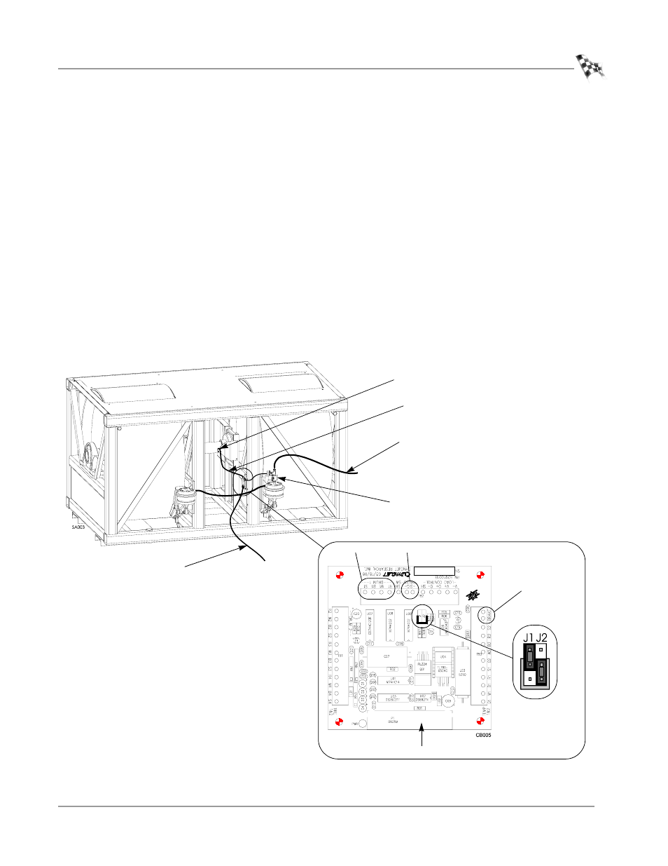
Plug the data acquisition cable into the optical pickup card on the dyno.
6
Attach the data acquisition cable coming from the optical pickup card on the dyno
to the Breakout board. The data acquisition cable has four wires which connect to
the wiring block labeled DRUM 1.
7
Attach the two black wires from the air brake control switch to the wiring block
labeled BRAKE on the Breakout board. Each wire may attach in either position.
8
Attach the yellow and black wires from the brake control to the wiring block
labeled PRESS on the Breakout board. Each wire may attach in either position.
9
The Breakout board jumper settings are preset, however, verify jumpers J1 and J2
are set for the standard air brake as shown in Figure 7.
Note: Make sure that the cables are clear from all moving parts.
10 Plug the 25-pin DynoWare Cable into the bottom of the Breakout board and
tighten the thumb screws.
Figure 7: Standard Air—Wiring
• Red wire connects to R1
• White wire connects to W1
• Black wire connects to B1
• Silver wire connects to S1
brake
press
standard air
jumper settings
DynoWare cable
pickup card
DynoWare cable
regulated air
data acquisition cable
air brake
control switch
drum 1