Installation instructions-cont – Code 3 LIT3 Mounting Kit User Manual
Page 5
5
Installation Instructions-Cont.
Note: If you are installing a Standard Version of the Mounting Kit, skip Steps 13 through 16 and proceed with Step 17
"Standard Version" at the bottom of page 6 of this manual.
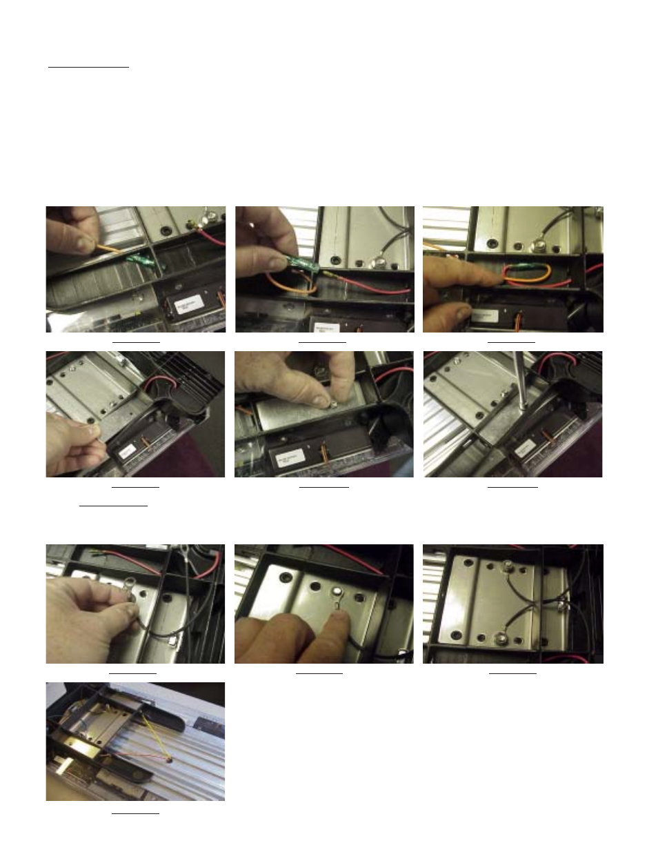
Step 13 Feed the ends of the power wires from the Lightbar through the holes in the Mounting Feet and into the Mounting Foot Wire Pockets (see
Figure 15) (See addendum for installation of the through-the-frame wires if your Lightbar is not equipped)
Step 14 Plug the ends of the power wires from the Lightbar into the power wires from the Mounting Feet (see Figure 16)
Step 15 Tuck the excess lengths of the power wires into the Mounting Foot Wire Pockets (see Figure 17)
Step 16 Position the wire covers into the Mounting Foot Wire Pockets (see Figure 18), insert a #8 X 1/4" Sheet Metal Screw into it's mounting hole
(see Figure 19), and tighten the Sheet Metal Screw with a 1/4" hex Driver or a #20 Torx bit (see Figure 20)
FIGURE
15
FIGURE
16
FIGURE
17
FIGURE
19
FIGURE
20
FIGURE
18
Step 17 Lighted Version Slip the Ring Terminal Ends of the Black Ground Wire under the rib on the Mounting Feet (see Figure 21), over
the ends of the
5/16"-18 Carriage bolts (see Figure 22) and position a 5/16" split washer and thread a 5/16"-18 Hex Nut onto each of the
Carriage Bolts (see Figure 23). At this point the assembly should look as shown in Figure 24.
FIGURE
21
FIGURE
22
FIGURE
23
FIGURE
24