Code 3 PSEDRL Flashers User Manual
Code 3 Hardware
DRL COMPATIBLE
100% SOLID STATE ALTERNATING ELECTRONIC FLASHER
COMPATIBLE WITH DAYTIME RUNNING LIGHTS
PSEDRL
Code 3 PSEDRL Solid State Flasher will operate a two or four
headlight system on any vehicle with a 12 Vdc negative ground
system.
NOTE
Please contact Code 3 before attempting to
install on any foreign vehicle (non-General
Motors, Ford or Chrysler).
A properly installed PSEDRL will alternate the vehicle's head-
lights at 1.9 hertz.
When used at night, the low beam head lights remain ON for
proper illumination while the high beams flash to gain atten-
tion and increase the vehicle's visibility. When the dimmer
switch is activated to high beam, the Flasher Systems "High
Beam Override" interrupts the Flasher sequence to allow for
normal high beam function. Flashing automatically resumes
when the dimmer switch is deactivated. The Flasher will auto-
matically turn OFF the vehicle's DRL when the Flasher is ac-
tivated.
INSTALLATION
MOUNTING: Mount the Flasher so that the maximum amount
of air will flow across it, typically in the front passenger side of
the engine compartment.
GREEN WIRE: Connect to a convenient reliable ground.
NOTE
Always connect the green wire FIRST when
installing and disconnect LAST when
removing.
BLUE & YELLOW WIRE: Locate the wire that supplies power
to the passenger side high beam headlights. Cut this wire
approximately 10" to 12" from the back of the headlight. Con-
nect the yellow wire to the lead that returns to the passenger
side high beam. Connect the blue wire to the other piece of
cut wire. This will make the driver's side high beam flash.
RED WIRE: Connect to a powered switch. This switch will
only require 1/4 amp to activate the Flasher.
WHITE WIRE: Connect through a fuse to the positive post of
the battery or other high current power source. A 20 amp fuse
to be used with a two headlight system and a 30 amp on a
four headlight system.
WARNING
DO NOT CONNECT THE FLASHER
SYSTEM TO A CIRCUIT BREAKER OR
FUSIBLE LINK.
NOTE
DO NOT connect the red and white wires
together. The white wire must receive a
constant source of power at all times.
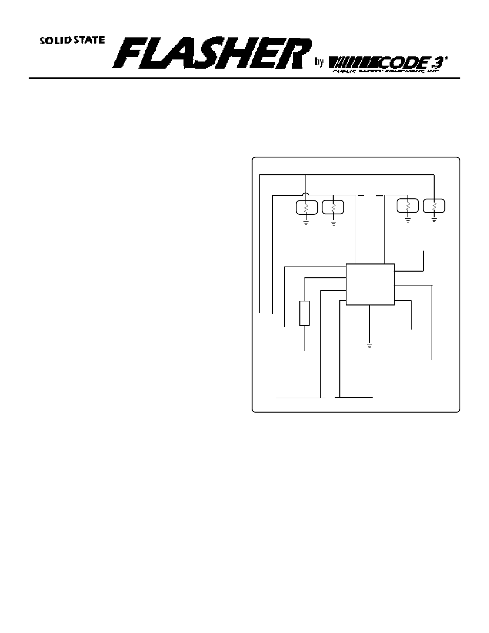
Wiring Schematic
•
•
BLUE
HIGH
X
X
[PASSENGER SIDE]
[DRIVER SIDE]
LOW
HIGH
YELLOW
PINK
GREEN
ORANGE
LOW BEAM WIRE
HIGH BEAM WIRE
FUSE
RED
WHITE
LOW
CONTROL
SWITCH
IGNITION
RUN WIRE
DRL
OVERRIDE
(optional)
WHITE/RED
BLACK
TO
BATTERY
PLUS
•
•
X X
CUT
CUT
TO MARKER
LIGHT WIRE
(optional)
ORANGE
SOLID STATE
FLASHER
VEHICLE'S
DRL WIRE