Installation instructions-cont – Code 3 LIT3 Mounting Kit User Manual
Page 4
4
Installation Instructions-Cont.
Note: The following Steps 9 through 13 are the same for both Lighted Mounting Kits and Standard Kits (The Lighted Version is
shown)
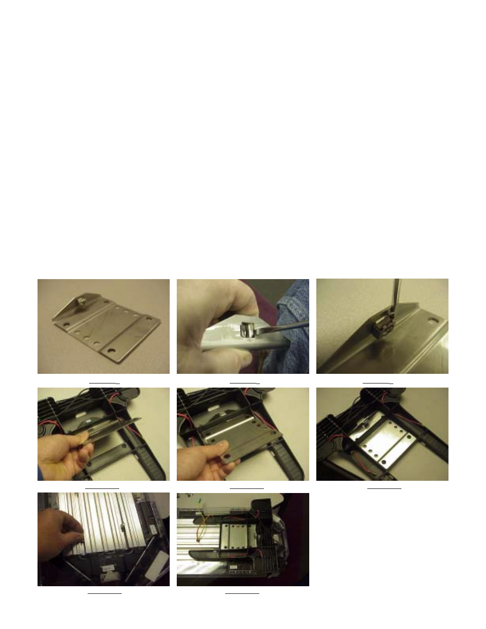
Note: Before proceeding with Step 9, make sure that the cage nuts are installed on the interior side of the
Stainless Steel Mounting Plates as shown in Figure 7 below. If the cage nut is not in the hole, slip one of the
ears of the cage nut into the square hole and use a screwdriver on the opposite side like a shoehorn to install
the cage nut into the hole as shown in Figure 8. If, after the cage nut is installed, the nut seems overly loose or
ready to fall out, use a slender screwdriver to pry the ears of the cage nut outward as shown in Figure 9 to
insure that it is retained during the remainder of the installation.
Step 9 Making sure any wires are out of the way on the Lighted Version of the Mounting Foot, position a Stainless Steel Mounting Plate through
the slot in the mounting foot (see Figures 10& 11) and into position over the locating bosses on each mounting foot (see Figure 12). Note: The
cage nut must be positioned as shown on the interior side of the mounting plate.
Step 10 Lay the Lightbar upside down on a clean, flat, padded surface (to protect the lenses from being scratched).
Step 11Slide (2) of the 5/16"-18 Carriage bolts on each side of the Lightbar into the slots in the lightbar's frame (see Figure 13).
Step 12 Position a Mounting Foot on each side of the Lightbar over the carriage bolts (see Figure 14).
FIGURE
7
FIGURE
8
FIGURE
9
FIGURE
10
FIGURE
11
FIGURE
12
FIGURE
13
FIGURE
14