Installation instructions – Code 3 LIT3 Mounting Kit User Manual
Page 3
3
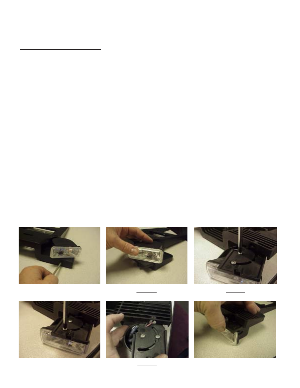
FIGURE 1
Installation Instructions
Installer Note: If
the LIT3 Mounting Kit being installed is a Lighted Version, proceed with the following steps! If the
Mounting Kit being installed is the Standard Version, skip Steps 1 through 8 and start with Step 9 on page 4 of this manual!
LIT3 Mounting Kit - Lighted Version
Step 1 Make sure the lightheads on the Mounting Kit are positioned in the desired location and orientation with respect to the Lightbar
(Example: Takedowns aimed toward the front, Alley Lights aimed toward the sides, and or Lightheads angled as desired, etc.) If the
location or orientation of the lightheads is O.K. skip Steps 2 through 8 and continue on from Step 9.
Step 2 If the location or orientation of the Lightheads must be adjusted, remove the #6 X 1/2" Slide Retention Screw with a #15 Torx Driver
(see Figure 1).
Note: The the 55 Watt Takedown lights are shown in the photos in Figures 1 through 6 below but the steps are the same for
the 3 LED OPTIX Lightheads!
Step 3 Pull out the Lighthead/Slide Shelf (see Figure 2).
Step 4 With the Lighthead/Slide Shelf removed, loosen the #8-32 X 1/4" Long Lighthead Mounting Screw with a #2 Phillips screwdriver (see
Figure 3). Note: This is the screw that the Lighthead Pivots on.
Step 5 Loosen the #8-32 X 1/4" Long Lighthead Mounting Screw closest to the front of the Lighthead's Lens (see Figure 4). Note: This is
the screw that locks and holds the Lighthead in position.
Step 6 Rotate the light on the slide shelf to the desired position and retighten the two Lighthead Mounting Screws. Note: It may be
necessary to remove the front Lighthead Mounting Screw shown in Figure 4 to bypass the support rib and then replace it
when the desired position is achieved.
Step 7 Tuck the wire connecters and the wires back into the Lighthead Cover leaving as little wire out of the cover as possible and making
sure thay are still engaged in the T-Slot in the slide shelf (see Figure 5). Carefully slide the Light Head Slide Shelf back into position while
guiding the wires into the gap provided between the Slide Shelf and the Mounting Foot (see Figure 6). Care should be taken to not pinch the
wires at the rear of the slide shelf.
Step 8 Replace the #6 X 1/2" Slide Retention Screw with a #15 Torx Driver again as shown in Figure 1.
FIGURE
2
FIGURE
3
FIGURE 4
FIGURE
5
FIGURE 6