Bracket, Controls in detail – Nikon os Speedlight SB-102 User Manual
Page 17
Attention! The text in this document has been recognized automatically. To view the original document, you can use the "Original mode".
CONTROLS IN DETAIL
Nikonos
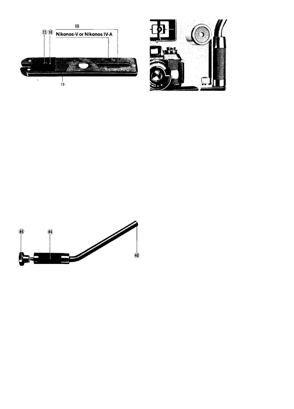
Bracket @
As indicated in the diagram there are two positions for
the bracket screw ®; one for Nikonos-V and Nikonos
IV-A and another for the Nikonos III. To reposition the
bracket screw, unscrew it, then screw it back into the
hole or the threaded end of the bracket slot ®. Once
screwed Into the bracket slot, the bracket screw can be
moved to any position.
The larger hole In the center allows the sync cord to be
connected through the bracket to the Nikonos III.
The small hole that goes completely through the bracket
is the sensor holder socket ®. When a plastic frame
finder or optical underwater viewfinder Is mounted on
the camera’s accessory shoe, the optional sensor
holder Is used to attach the Sensor Unit SU-101 to the
speedlight bracket. To attach, align the sensor holder
positioning pin ® on the top 6f the bracket with the hole
Sensor Unit SU-101
attached to the
bracket with the
sensor holder.
in the sensor holder; then screw the knob clockwise
until it is tight.
The small hole on the underside of the bracket is the
tripod socket @.
•
W hen the bracket and arm are attached to the Nikonos IV-A, certain
optical
tinder
models
for
older
UW -Nikkor
15mm
1/2.8
lenses
cannot
be
attached.
If
this
presents
a
problem
tor
you.
authorized
Nikon
dealers and service centers can perform the necessary modification.
Arm ®
To attach the arm to the joint @, insert the arm position
ing screw ® into the slot in the joint from either side.
Align the arm positioning screw with the arm positioning
index @ on the joint by turning the arm 90°. After align
ing the arm positioning screw with the arm positioning
index, turn the joint lever (§) clockwise as far as it will go
to lock the arm into position. When the arm is attached
in this manner, the speedlight’s axis will always inter
sect with the lens's optical axis, even if the flash head is
moved up or down on the arm. (Normally, the joint is
locked at the top of the arm.) Before diving, be sure the
joint knob ® and joint lever are locked tightly.
To attach the arm to the bracket, turn the arm knob ®
counterclockwise as far as it will go to loosen it (the two
bracket positioning pins on the bottom of the grip @ will
be visible). Slide the open end of the bracket between
the arm knob and the grip, seat the two bracket posi
tioning pins in the two indentations on the bracket, and
turn the arm knob clockwise as far as it will go to lock
the bracket into position. The correct arm/bracket posi
tion is with the two washers on the underside of the
bracket, the rubber side of the bracket facing up, and
the flat side of the grip perpendicular to the bracket.
17