Basic operations —continued, Connect the sync ■ cord® to the camera, 23 rernove the synchro ■ socket cover (d – Nikon os Speedlight SB-102 User Manual
Page 12: 25 confirm the position ■ of thefiash head
Attention! The text in this document has been recognized automatically. To view the original document, you can use the "Original mode".
BASIC OPERATIONS —continued.
OO
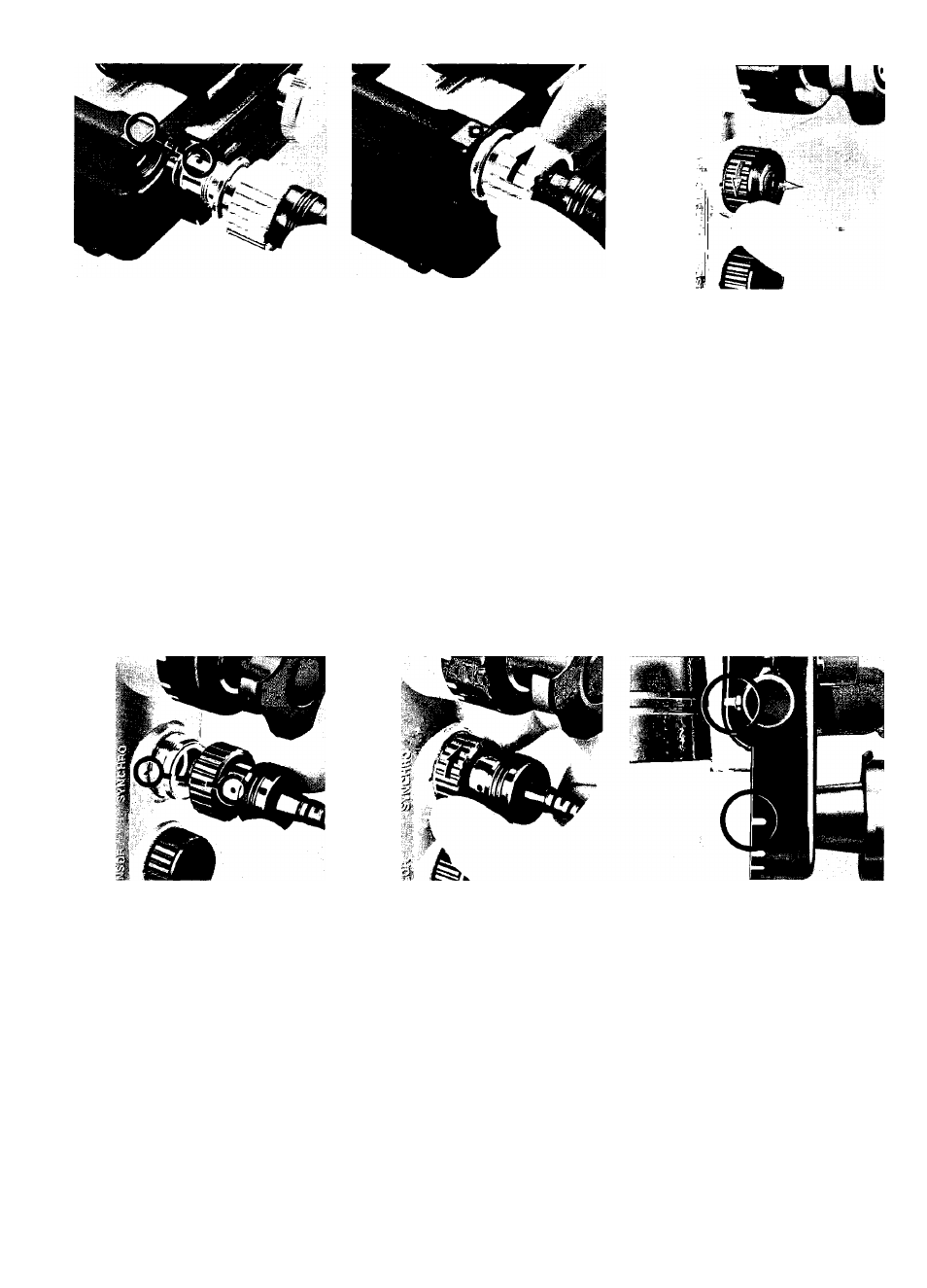
Connect the sync
■ cord® to the
camera.
Remove the dust-proof plastic cap
from the sync cord’s camera plug
(silver). Insert the camera plug in
the camera’s flash socket after
aligning the white index on the flash
sync socket with the red index on
the camera plug. When the camera
plug is inserted, turn its locking ring
clockwise as far as it will go to
secure the plug.
Check the 0-ring; Before con
necting the camera plug to the
camera, examine the plug’s 0-ring
for dust and scratches and be sure
it is properly seated and lubricated.
• Do
not apply excessive force to the sync
cord's
camera
plug,
and
avoid
twisting
the
cord as much as possible.
23
Rernove the synchro
■ socket cover (D.
Turn the synchro socket cover
counterclockwise, then pull it up.
24
Connect the sync
cord to the SB-102.
Remove the dust-proof plastic cap
from the sync cord’s speedlight
plug (black). Insert the speedlight
plug into the synchro socket after
aligning the synchro socket index
© with the red index on the speed-
light plug. When the speedlight plug
is inserted, turn its locking ring
clockwise as far as it will go to
secure the plug.
Check the 0-ring: Before connect
ing the speedlight plug to the
speedlight, examine the plug’s
0-ring for dust and scratches and
be sure it is properly seated and
lubricated.
•
To keep the sync cord out of the way while
shooting, attach it to the hook of the cord
fastening hanger.
25
Confirm the position
■ of thefiash head.
Confirm that the arm positioning
screw is aligned with the arm posi
tioning index, the flash head posi
tioning index is aligned with the
“normal” position mark on the flash
head positioning scale, and the
flash head is facing in the same
direction as the camera's lens. If
the arm positioning screw is not
properly aligned, loosen the joint
lever to reposition it. If the flash
head positioning index is not pro
perly aligned loosen the joint knob
to reposition it.
• See page 18 for information about position
ing
the
flash
head
for
close-up
shooting
within approximately 1m (3.3 ft).
12