Hole alignment alternative, Figure 3, Installation step 12 – Craftsman 139.53675SRT User Manual
Page 26
Attention! The text in this document has been recognized automatically. To view the original document, you can use the "Original mode".
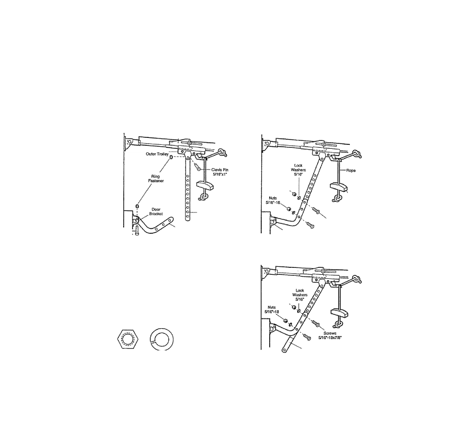
Installation Step 12
Connect Door Arm to Trolley
Follow Instructions which apply to your door
type as Illustrated below and on page 27,
Make sure garage door is fully closed. Pull the emergency release handle to disconnect the outer trolley
from the inner trolley. Slide the outer trolley back (away from the door) aboirt 2" as shown In
Rgures 1,2 and 3.
Rgure 1:
• Fasten straight door arm section to outer trolley
with the the 5/16*xr clevis pin. Secure the
connection with a ring fastener.
« Fasten curved door arm to the door bracket in the
same way, using the
S/IS'xl-IM" clevis pin.
inner Troilsy
Rgure 2:
• Bring arm sections together. Rnd two pairs of holes
that line up and join sections. Select holes as far
apart as possible to increase door arm rigidity.
Cle«a
Pin
S/16M-1/4'
Straight
Door Arm
Cusved
i3oor Arm
igure 1
Eni0f||ency
Heiease
Handle
Scmws
sne'-iew/s*
Door Bracket
Figure 2
Hole Alignment Alternative
Figure 3:
• If holes In curved arm are
above
holes in straiaht
arm, disconnect straight arm. Cut about 6** from
the solid end. Reconnect to trolley with
cut end
down
as shown.
• Bring arm sections together.
• Rnd two pairs of holes that line up and join with
screws, lock washers and nuts.
Hardware Shown Actual Size
O
Nutsns'-IB Lock Washer S/1 S' Ring Fastener
o
' CieHs Pin
m e 'x V
{Trolley)
o
Clevis Pin
Hex Screw
(Door Bracket) 5/l6‘-iax7/B*
Cut This End
Figure 3
Proceed to Adjustment Step 1, page 28, Trolley will re-engage automatically when the opener is operated.
26