Adjustments, Aligning the arm for cross cuts, A warning – Craftsman 315.220381 User Manual
Page 37
Attention! The text in this document has been recognized automatically. To view the original document, you can use the "Original mode".
ADJUSTMENTS
ALIGNING THE ARM FOR CROSS CUTS
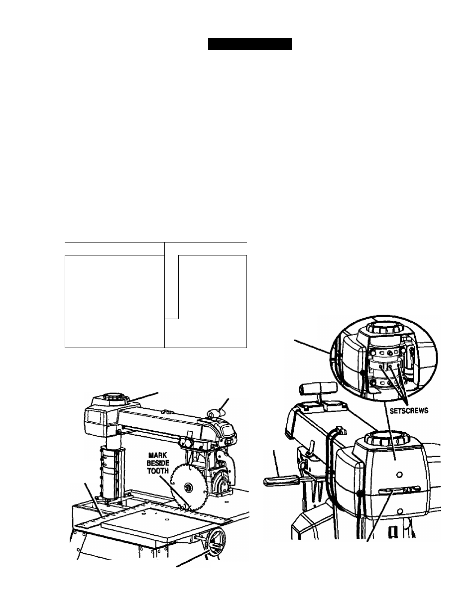
See Figures 29A - 29C.
This procedure checks whether the arm is exactly O'
for cross cut travel by checking the blade against the
tabie and the miter indicator. Remove the rear table,
spacer table, and fence, but leave the front table in
place. You will need a framing square, a 3/16 in. hex
key, and a pencil.
A WARNING:
Be sure the saw is unplugged
before performing these adjustments. Accidental
start-up could result in serious personal injury.
■ First check the framing square by fitting one side
against the back edge of the table. Lightly draw a
line on the table along the edge of the square in
the middle of the table. Flip the square over. If the
edge still matches the line with no gaps or over
laps, the square is taie.
■
1
[
1
1 1
r
Y
1
1
\
» 1
\
1 ■
STRAIGHT
■ ■
EDGE
DRAW A STRAIGHT-----------
-
—f
UNE ALONG THIS EDGE ; ;
^\^FRAMING
__________________
2
SQUARE
THERE SHOULD BE NO GAP HERE WHEN
SQUARE IS FLIPPED OVER TO DOTTED POSITION
Fig. 29A
MITER INDICATOR
¿RM
LOCK KNOB
FRAMING
SQUARE
ELEVATING
HANDWHEEL
Release the arm lock knob. Position the arm
straight forward (O') and leave it unlocked.
Lower the arm writh the elevating handwheel until
the saw blade just clears the front table. Lock the
yoke lock handle (right side of saw, below yoke)
and the bevel lock lever.
Place the framing square on the table and position
one edge of the square firmly against the back
edge of the table. Position the other leg of the
square against the blade until it rests beside but not
touching a tooth, \With a pencil, mark beside this
tooth.
Slowly move the yoke assembly forward and
backward along the arm and against the square
without rotating the blade. If the mark moves into or
away from the square, adjust the arm with the
following steps.
At the back of the column, loosen the three set
screws with a 3/16 in. hex key and position the arm
as needed to align with the framing square.
I Lock the arm lock knob and retighten the three
setscrews. Recheck the cross cut travel with the
blade against the framing square.
I Set the miter indicator on top of the column to 0*
I Replace the fence, spacer table, rear table, and
table clamps.
REAR COVER
REMOVED FOR
CUflUY
YOKE
LOCK
HANDLE
SETSCREWS
Fig. 29C
Fig. 29B
37
CRRFTIMAr RADIAL SAW 315.220381