Assembly, Installing the yoke assembly, Warning – Craftsman 315.220381 User Manual
Page 24
Attention! The text in this document has been recognized automatically. To view the original document, you can use the "Original mode".
ASSEMBLY
The yoke rides in the carriage below the arm and
supports the motor, the blade guard, and the blade.
Install the yoke assembly from the front of the arm.
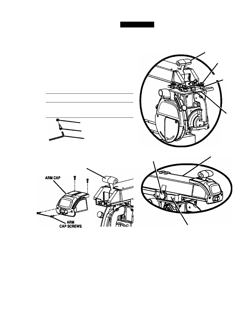
■ Remove the carriage stop screw and lockwasher
from below the front of the arm with a 1/4 in. hex
key. See Figure 13A.
ARM VIEWED FROM BELOW
INSTALLING THE YOKE ASSEMBLY
See Figures 13A - 13C.
FOR CLARITY, CARRIAGE COVERS AND CARRIAGE LOCK
KNOB ARE NOT SHOWN IN ILLUSTRA'RON
ARM LOCK KNOB
BEARINGS (4)
CARRIAGE
n
--------- -------
LOCKWASHER
CARRIAGE STOP SCREW
1/4 in. HEX KEY Fig.13A
Remove the arm cap screws and arm cap from the
front of the arm with a philltps screwdriver. See
Figure 13B.
YOKE
CARRIAGE
LOCK KNOB
ARM
ARM LOCK KNOB
Fig, 13B
Remove and discard the two motor setscrews in
the bottom of the motor. They are for shipping
purposes only.
Using the elevating handwheel, raise the arm 3
inches and remove the packing material.
Lock the arm with the arm lock knob, located on top
of the front of the arm, so the arm doesn’t swing
while you are mounting the yoke assembly.
Pick up the yoke assembly and carefully slip it onto
the carriage track below the arm. Keep it parallel
with the arm so bearings slide In smoothly. See
Figure 13C.
CARRIAGE COVER
13C
Reinstall the carriage stop screw, the lockwasher,
arm cap, and arm cap screws. Tighten all screws
securely.
^ WARNING:
Once the yoke assembly is on the
* carriage track, reinstall the arm cap, №e arm cap
screws, the carriage stop screw, and the
lockwasher. Do not risk serious injury or damage
to the saw by falling to replace these parts.
Tighten the carriage lock knob, on the carriage
cover on the left of the arm, to lock the yoke
assembly in place.
CRRFTSMRir RADIAL SAW 315.220381
24