Taylor-Wharton Auto Fill Laser Pak User Manual
Page 6
6
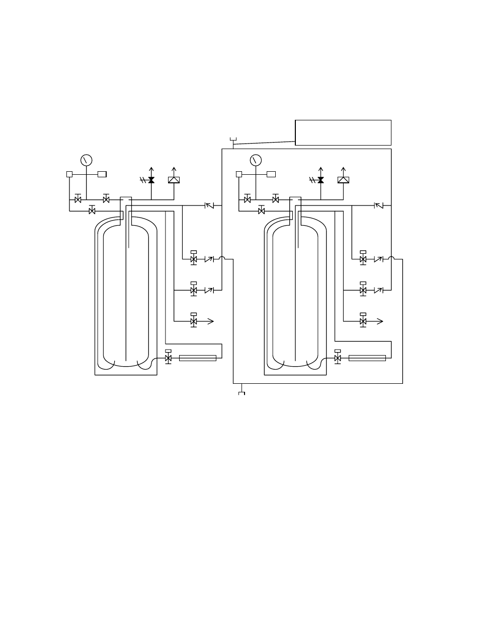
PIPING CIRCUITS
The following paragraphs describe the operation of the piping circuits of the system. The descriptions refer to
the main components of each circuit and are grouped by function. Reference the piping schematic below and
in the general arrangement drawing for the component designations. Round stainless steel tags attached to the
system identify the components. Component tags ending with “A” identify components associated to vessel
A; tags ending with “B” identify components associated to vessel B. These component and circuit
descriptions should be understood before attempting operation.
Legend
CN-1
Bulk Tank Connection
PB
Pressure Builder
CN-2
Vaporizer Connection
V-1
Liquid Use Solenoid Valve
CV-1
Liquid Use Check Valve
V-2
Vent to Bulk Tank Solenoid Valve
CV-2
Vent to Bulk Tank Check Valve
V-3
Vent Solenoid Valve
CV-3
Fill Check Valve
V-4
Pressure Building Solenoid Valve
BD
Rupture Disc
V-5
Liquid Phase Isolation Valve
PI
Vessel Pressure Gauge
V-6
Vapor Phase Isolation Valve
PT-1
Liquid Level Transmitter
V-7
Equalization Valve
PT-2
Vessel Pressure Transmitter
RV-1
ASME Relief Valve
PT-3
Bulk Tank Pressure Transmitter
Figure 1: System Piping Schematic
PB-A
V-4A
V-2A
V-1A CV-1A
CV-2A
CV-3A
BD-A
RV-1A
V-6A
V-5A
V-3A
V-7A
PI-A
PT-2A
PT-1A
PT-1B
PI-B
PT-2B
V-5B
V-7B
V-6B
RV-1B BD-B
CV-3B
CV-1B
V-1B
V-2B CV-2B
V-3B
PB-B
V-4B
CN-2
CN-1
Vessel “B”
Vessel “A”
AF55-0C00 has a
strainer following the
bulk connection