Taylor-Wharton Auto Fill Laser Pak User Manual
Page 12
12
Instrumentation Circuits
The system instrumentation consists of liquid level transmitter, pressure transmitter, pressure gauges, and
isolation valves. The vessel pressure gauges (PI) display the inner container pressure in pounds-per-square-
inch and kilopascals. A pressure gauge is piped to each of the vessels.
The liquid level transmitters (PT-1) measure the liquid level in the vessels. This instrument is a differential
pressure transmitter. Liquid inside the vessel creates slightly greater pressure at the bottom of the vessel than
at the top. The pressure differential increases with increasing liquid content. By measuring this differential
pressure, the liquid level is determined. One of these instruments is supplied for each of the vessels.
Three pressure transmitters monitor pressure in each of the vessels (PT-2) and the bulk tank (PT-3). The bulk
tank pressure transmitter is located inside the Auto-Fill Laser Pak control panel. The controller uses these
inputs to control supply pressure and venting to the bulk tank.
Isolation valves allow the instruments to be replaced without emptying and depressurizing the system.
The vapor phase isolation valve (V-6) isolates the liquid level transmitters, pressure gauges, and pressure
transmitters from the line (low pressure) connected to top of the inner vessel. The liquid phase isolation
valve (V-5) isolates the same instruments from the line (high pressure) connected to the bottom of the
inner vessel. The equalization valve (V-7) is used to equalize the pressure between the high and low-
pressure sides of the liquid level transmitter.
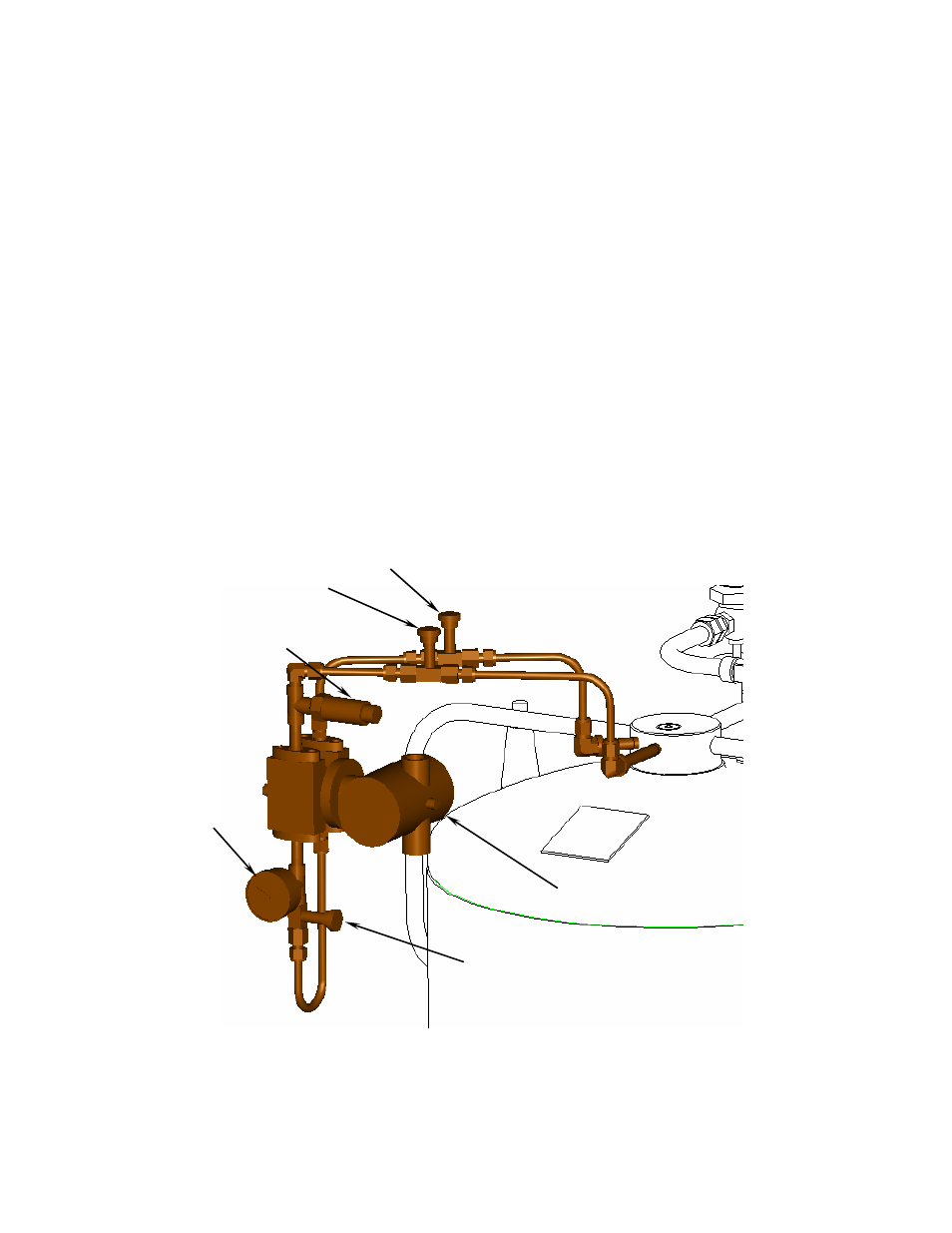
Figure 7: Instrumentation circuit for vessel B highlighted in blue.
(Frame and wiring omitted from view for clarity.)
V-7B
V-6B
V-5B
PI-B
PT-2B
PT-1B