Warning – Qmark TBX - Tool Box Heater User Manual
Page 2
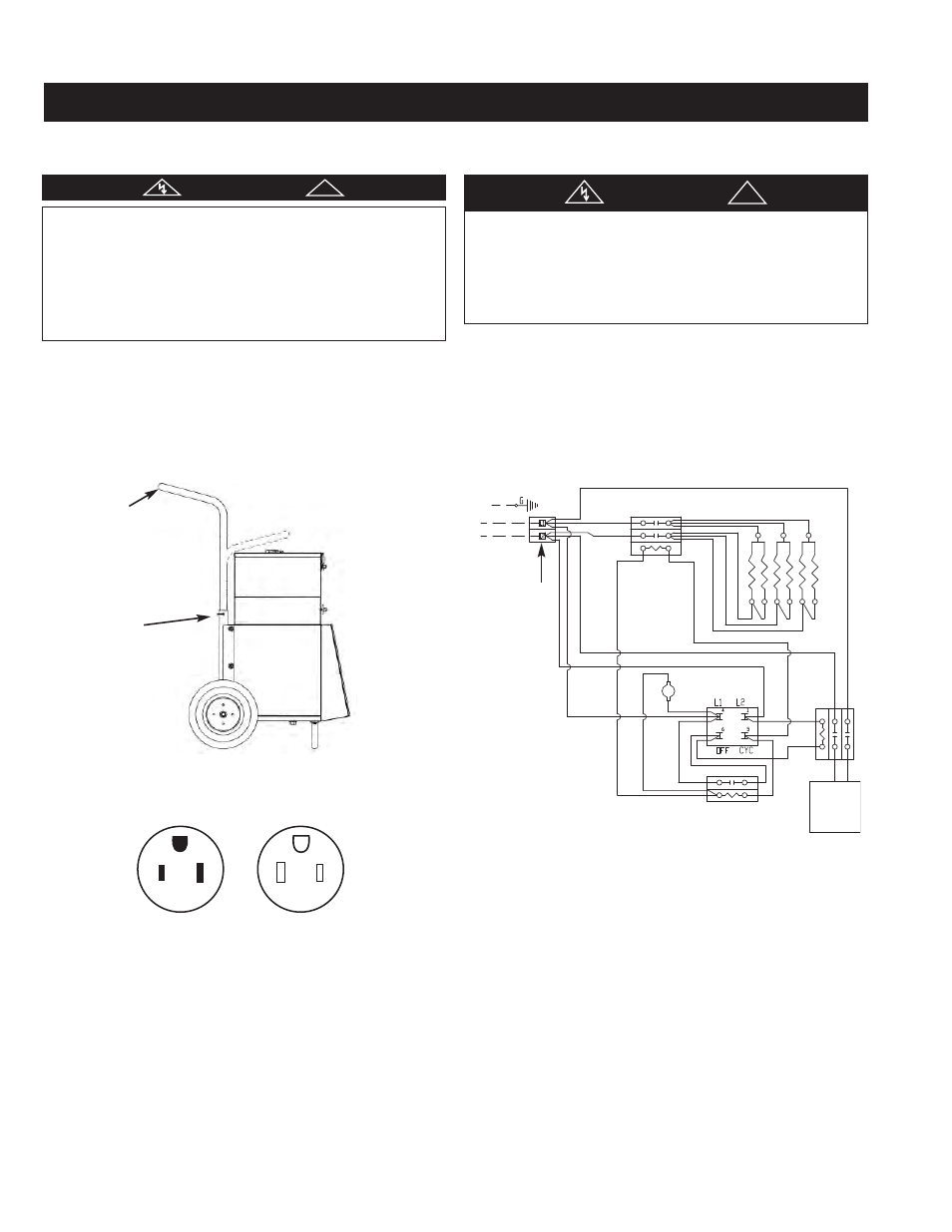
ASSEMBLY INSTRUCTIONS
This heater is shipped partially assembled. The handle is
shipped securely under the heater to avoid damage. Take han-
dle and insert in the vertical position as shown in figure 1.
Secure handle using the retaining clips supplied. The heater is
now fully assembled.
WIRING INSTRUCTIONS:
1. Use heater only on the voltage and frequency specified on
the nameplate.
2. Heater includes a cord with plug. Receptacle must be
NEMA 6-50R to match with unit plug (see Figure 2).
3. Insure plug fits tightly into outlet. A loose fit can cause
overheating and damage to the plug.
THERMOSTAT AND FAN CONTROL OPERATION:
Heaters include a built in thermostat to control the heater and
fan only operation. When in the full counterclockwise (OFF)
position, both the heater and fan are deenergized. Turning the
knob clockwise from the OFF position to the FAN position will
energize the fan only, for use in summer cooling. Turned further
in the clockwise direction will operate the heater, with the high-
est temperature setting in the extreme clockwise position. The
temerature range in the heater mode is approximately 40°F at
the low setting to approximately 100°F at the highest setting.
WARNING
RISK OF FIRE OR DISCOLORATION OF TEMPERATURE
SENSITIVE FABRICS. DO NOT USE AS A RESIDENTIAL OR
HOUSEHOLD HEATER. KEEP COMBUSTIBLE MATERIAL
AND SUCH FABRICS AWAY FROM HEATER. HEATERS IN
THE HEAT MODE SHOULD NOT BE OPERATED IN ROOM
TEMPERATURES ABOVE 80°F. FAN MOTOR IS NOT
DESIGNED TO OPERATE IN AMBIENTS BELOW -40°F.
!
WARNING
ELECTRIC SHOCK HAZARD. DISCONNECT ALL POWER
BEFORE INSTALLING OR SERVICING HEATER. FAILURE
TO DO SO COULD RESULT IN PERSONAL INJURY OR
PROPERTY DAMAGE. HEATER MUST BE EFFECTIVELY
GROUNDED IN ACCORDANCE WITH THE NATIONAL
ELECTRICAL CODE, NFPA 70.V
!
Figure 1
Retaining Clip
Handle in full
upright position
G
G
Plug
NEMA 6-50P
Receptacle
NEMA 6-50R
Figure 2
MODEL
FAN
TEMP
SHIP
CORD
NUMBER
KW
VOLTS
BTUH
PH
AMPS
OUTPUT
RISE
WT
SET
TBX104
9.5
240
32,424
1
39.44
625 CFM
48°F @ 77°F
117 lbs
INCLUDED (8-FT)
TBX754
7.5
240
25,598
1
31.14
625 CFM
38°F @ 77°F
110 lbs
INCLUDED (8-FT)
Specifications
Power Cord
(Supply)
PowerBoard
(240 V)
Limit Contactor
Limit
Thermostat
Motor
Cont
Motor
Time Heat Relay
Element
Figure 3