Warning, Figure 6. control terminal board – Qmark MUH - Horizontal / Downflow Unit Heaters User Manual
Page 2
INSTALLATION OF HEAT RECOVERY THERMOSTAT
HRTA, 3UG63 and 2YU90
NOTE: This accessory cannot be installed on heaters equipped
with built-in single-pole or two-stage thermostats.
(For heaters with 24 Volt Control Circuit refer to Fig. 7 and proceed
to step 1. For heaters with Line Voltage Control refer to Fig. 6 and
proceed to step 3.)
1. Mount relay in baffle compartment with two No. 8 mounting screws
as shown in Figure 4.
2. Connect the lead wires from the relay to the control terminal board
as shown in Figure 7. Each lead wire is marked for proper terminal
location; connect lead wires as indicated.
3. Remove 5/16" (7.9mm) knockout from back of heater and route capillary
tube through hole (See Figure 1).
4. Install thermostat bulb clip in slot provided in the back panel of the
heater. Secure capillary bulb in clip.
5. Press on left side of logo label on the front of heater to locate shaft
and screw holes. Punch holes through label.
6. Install heat recovery thermostat as shown in Figure 2, coiling any
excess capillary tubing inside the heater.
7. Use the wire tie to hold the thermostat leads to other wiring at
approximately the midpoint of the leads between control terminal
board and thermostat.
8. Refer to wiring diagram, Figure 6 or Figure 7 for wiring procedure.
9. Install knob by pushing onto the thermostat shaft.
10. Set thermostat for desired turn-on temperature. Full counter-clock-
wise rotation of the knob is approximately 70°F (21° C). Full
clockwise rotation of the knob is approximately 120°F (49° C).
INSTALLATION OF 25 AMP AND 60 AMP
POWER DISCONNECT SWITCH
DS25, DS60, 3UG68, 3UG69, 2YU93 and 2YU94
1. Use copper conductor supply wire only when using these switches.
2. Remove the 5/8" (16mm) knockout and the two knockout slots from
back of heater, below OFF-ON markings.
3. Install power disconnect switch with two mounting screws as shown
in Figure 5.
4. Install the knob with the pointer position at the "OFF" position mark-
ing when the switch is rotated to the full counterclockwise position.
5. Before connecting the wires of the switch, check the pointer index.
Check to be sure the pointer end of the knob points to "OFF" when
the switch is rotated full counterclockwise. It may be necessary to
rotate the switch 180° to index the pointer knob.
6. Refer to wiring diagram, Figure 8, for wiring procedure.
(NOTE: For single-phase, remove and discard leads "L2" and "S2").
OFF
ON
MOUNTING
SCREWS (2)
POWER
DISCONNECT
SWITCH
KNOB
BACK OF
HEATER
Figure 5. Installation of Power Disconnect Switch
Figure 7. Control Terminal Board for RFS1 and RFS2
(for Heaters with Contactors)
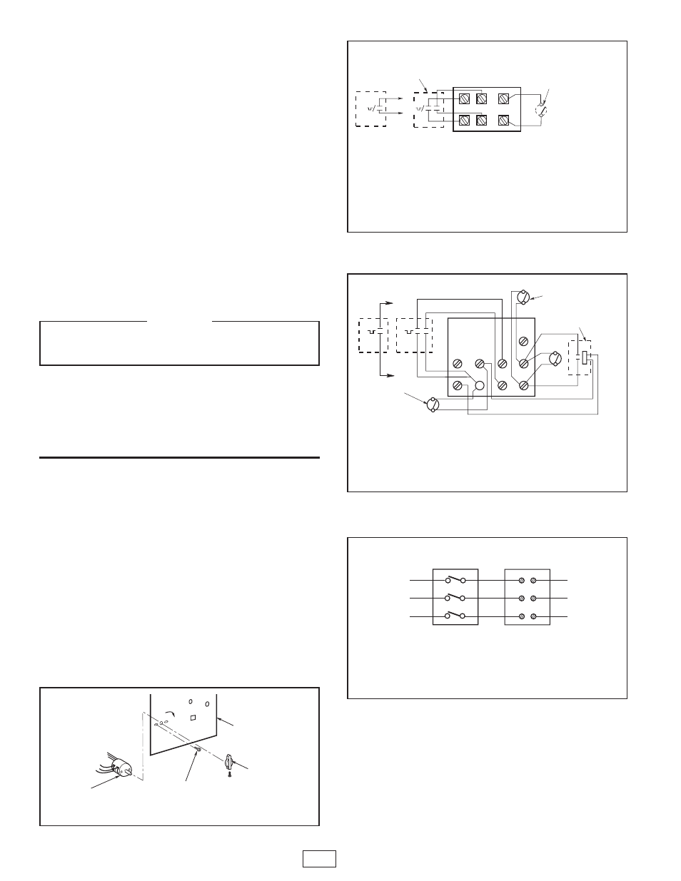
Figure 6. Control Terminal Board
(for Heaters without Contactors)
NOTES:
1. THIS STYLE CONTROL TERMINAL BOARD USED WITH MODELS 3KW AND 5KW UNITS
(208V, 240V AND 277V ONLY).
2. WHEN UNIT IS WIRED FOR SINGLE PHASE, JUMPER H1 TO H2. IF SINGLE POLE
THERMOSTAT IS USED WITH SINGLE PHASE UNIT, CONNECT THERMOSTAT LEADS TO
P1 AND H1.
3. EXTERNAL LINE VOLTAGE THERMOSTAT SHOULD BE TREATED AS SINGLE STAGE ONLY.
S
F2
H2
F1
H1
P2
P1
RED
BLK
RED
BLK
MT-2
MT-1
2-STAGE
INTERNAL
THERMOSTAT
HEAT RECOVERY THERMOSTAT HRTA
REMOTE SUMMER FAN SWITCH RFS1
SUMMER FAN SWITCH FS (MANUAL)
T
BLACK
TO H1
RED
TO P1
OR
2E569
2YU33
3UG72
2YU95
3UG03, 2YU82
3UG63, 2YU90
Figure 8. Power Disconnect Switch Wiring Diagram for DS25,
DS60, 3UG68, 3UG69 2YU93 and 2YU94
SEE
NOTE 1
TERMINAL
BLOCK
POWER
DISCONNECT
SWITCH
S1
S2
S3
L1
L2
L3
TO
POWER
SUPPLY
SEE
NOTE 2
NOTES:
1. THIS ILLUSTRATION SHOWS WIRING HOOK UP FOR THREE PHASE
SERVICE. REMOVE LEAD WIRES MARKED L2 AND S2 WHEN USING
ONE PHASE POWER SERVICE.
2. USE COPPER SUPPLY WIRE ONLY WITH THIS SWITCH.
NOTES:
1. THIS STYLE CONTROL TERMINAL BOARD USED WITH ALL MODELS EXCEPT 3KW AND 5KW
UNITS (208V, 240V AND 277V ONLY).
2. REMOVE JUMPER W1 TO W2 WHEN 2-STAGE THERMOSTAT IS USED.
3. *ONLY ONE OF THESE ACCESSORIES MAY BE INSTALLED IN A SINGLE HEATER.
4. EXTERNAL LINE VOLTAGE THERMOSTATS SHOULD BE TREATED AS SINGLE STAGE ONLY.
REMOTE SUMMER
FAN SWITCH RFS1
S
S
*FAN RELAY (FOR HEAT RECOVERY
THERMOSTAT
HRTA OR REMOTE
PILOT DUTY FAN SWITCH RFS2)
TR
F1
W2
G
F2
W1
R
C
*SUMMER
FAN SWITCH
BLACK
RED
BLACK
RED
HEAT RECOVERY
THERMOSTAT OR
REMOTE PILOT DUTY
FAN SWITCH
T
BLACK
TO W1
T
MT-2
2-STAGE
INTERNAL
THERMOSTAT
T
RED
TO R
MT-1
2E569
2YU33
3UG72
2YU95
TO PREVENT A POSSIBLE ELECTRICAL SHORT CIRCUIT OR
FIRE, KEEP CAPILLARY TUBING AWAY FROM INTERNAL
ELECTRICAL COMPONENTS.
WARNING
6/09
ECR 38318
5200-2298-502
2
470 Beauty Spot Rd. East
Bennettsville, SC 29512 USA