Qmark MSPH - Plenum Rated Unit Heater User Manual
Page 2
2
GENERAL INFORMATION:
The PRH Series plenum heaters are design certified by ETL to
Standard for Heating and Cooling Equipment ANSI / UL 1995,
CAN/CSA C22.2 No. 236-05, third edition. The PRH Series
plenum heaters are unique application heaters approved for
installation in a concealed space, an area between a finished
ceiling and drop ceiling, a plenum space or inside a plenum.
These series of heaters may be installed in areas that are not
readily accessible and may be installed with a duct system or
installed for free-air discharge. Always install units to operate
within the intended temperature rise, intended external static
pressure range and in the intended installation position (see
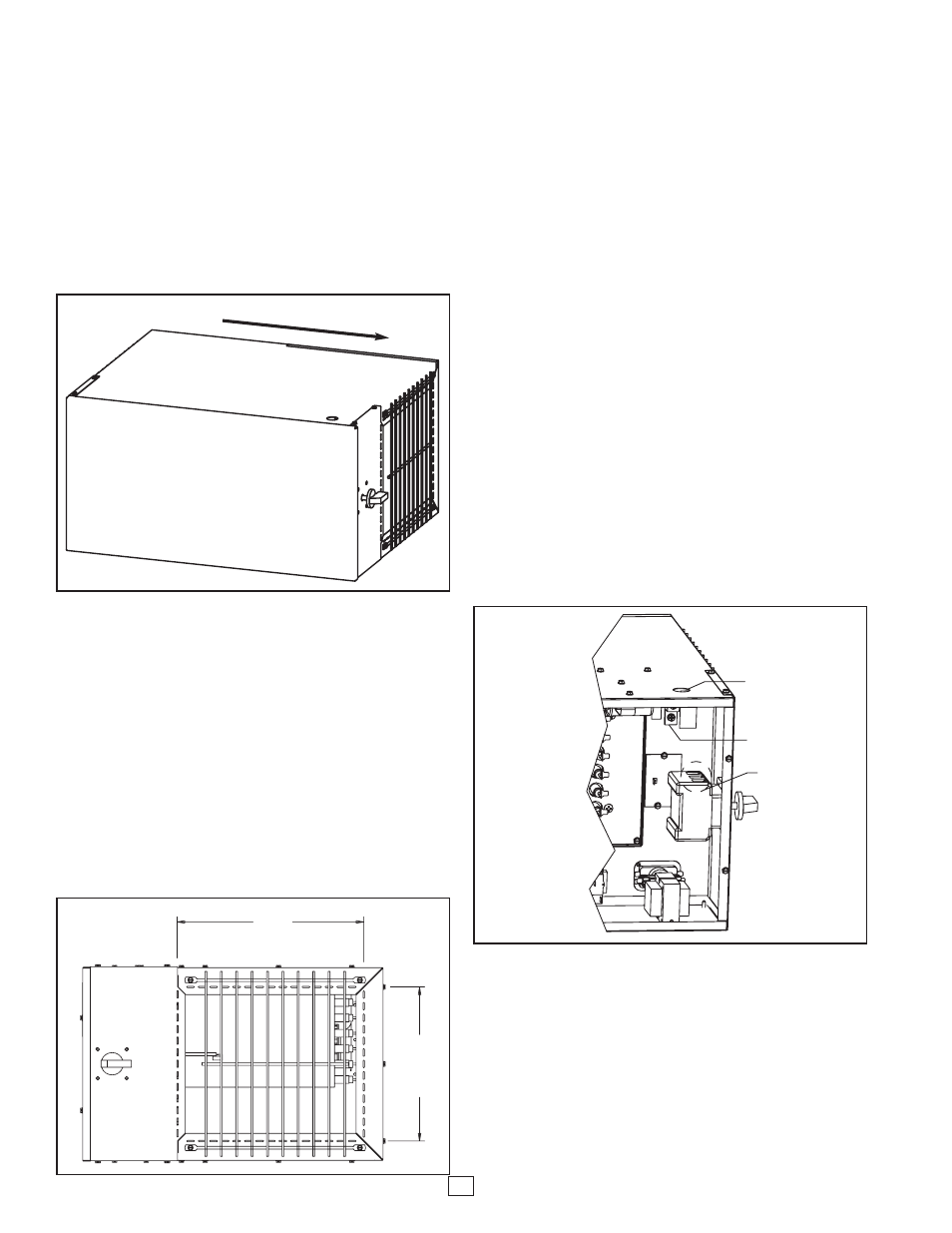
Figure 2 horizontal-right).
MOUNTING:
The PRH Series plenum heaters are intended to be mounted
in the horizontal-right installation position (see Figure 2) and in
a suspended manner. The unit can be rotated on its axis in
any position needed (can not be mounted vertically). Suspend
the unit from the building structure in a horizontal plane. Units
must be independently supported. Support channels or straps
are intended to be permanently attached to unit frame/housing.
Be careful not to obstruct access to control panel with support
channels or straps. DUCT CONNECTIONS / DUCTING:
The PRH Series plenum heaters may either be installed for
free-air discharge or with a duct system. The proper sizing of
warm air ducts is essential in providing satisfactory heating
operation. Ductwork should be in accordance with the latest
editions of NFPA-90B (Warm Air Heating and Air Conditioning
Systems) or Canadian equivalent. Every PRH model is
equipped with an inlet and outlet grille for free-air discharge.
Both grilles are intended to be removed when connecting to a
duct system. The inlet and outlet ends of the unit are
equipped with perforated flanges to aid in forming both inlet
and outlet duct flanges (see Figure 3).
These perforations will aid in forming a rectangular inlet and
outlet duct flange if they are desired for connection to the duct
system. The unit is designed for a rectangular flange duct con-
necting and the clear area around the flange is intended for
screw penetration. This feature aids in attaching the duct work
to the unit so that the ductwork may be fastened and sealed to
the unit.
CONTROL ACCESS:
The front door allows access to all the controls and compo-
nents within the unit. The unit is design certified for 0” clear-
ances however, while installing the unit, be careful not to
obstruct access to this control panel. This panel allows access
to the unit for making the power connection, the thermostat
connection and is intended to allow access to all the internal
components that make up the unit.
ELECTRICAL CONNECTIONS:
All field wiring must comply with NEC and local codes.
N
NO
OT
TE
E:: S
SE
EE
E P
PA
AG
GE
E 3
3 &
& 4
4 F
FO
OR
R W
WIIR
RIIN
NG
G D
DIIA
AG
GR
RA
AM
MS
S
All units are designed for a single point connection to supply
power to the fan and electric heater. The PRH series plenum
heaters are shipped standard with a 80 amp 3-pole disconnect
switch. Field power connections are made to the line side of
this disconnect switch (see Figure 4).
Each unit is equipped with a grounding lug for ground connec-
tion. The unit must be properly grounded to comply with NEC
and local codes. Before making the power connection, insure
that the line voltage to the unit matches the ratings located on
the nameplate of the unit. All units should have copper wire
sized for 125% of nameplate amperage. Disconnect the power
supply before wiring the unit and insure the disconnect switch
is in the OFF position while making power connections or ser-
vicing the unit. The unit cabinet has a 7/8” electrical knockout
for routing power supply to the disconnect switch (see
Specifications section for knockout location). Should the unit
require a larger electrical conduit connection, this electrical
knockout is intended to serve as the pilot hole in order to field
convert to larger electrical connections.
AIRFLOW DIRECTION
Figure 2
12” Small
11.64” Large
10”
Small
15.32”
Large
Figure 3
Electrical
Knocknot
Ground
Connection
Power
Connection
Figure 4