Installation of heater assembly and grille, Operation, 1950cm – Qmark LFK Series - Wall Heater User Manual
Page 3: Fig. 5 wiring diagrams
3. Power Supply Wiring
NOTE: Wiring Compartment Volume - 119in
3
(1950cm
3
).
a. Run correctly sized power supply cable into the area
of the upper right corner of the mounting frame.
NOTE: If the wiring is to run through the wall, cut a hole in
the area of the top of the back box. Run the supply wire
through this hole. Then remove the knockout from the
top of the box and proceed to step c.
b. Remove the knockout on the top side of the frame.
c. Feed the power supply cable through the frame allow-
ing 6" (152mm) of lead to remain inside the frame
d. Insert power supply cable through cable clamp, allow-
ing at least 6" (152mm) of leads to extend inside the
back box. Connect the blue lead wires of disconnect
switch to the supply wire leads using wire connectors.
(See wiring diagram, Fig. 5)
e. Ground the back box by connecting the supply ground
leadwire to the green ground screw located in the
inside top of the back box.
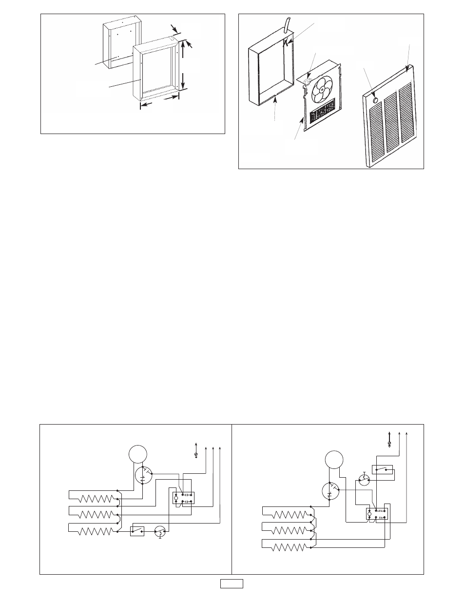
Installation of Heater Assembly and Grille
After back box is competely installed and no further con-
struction dirt is expected, clean debris from back box,
remove heater assembly from its carton, then refer to Figure
4 and proceed as follows:
1. Insert the heater assembly into back box, placing the
four mounting holes (with key-hole slots) over the
screws in the back box. Tighten all screws securely.
2. If surface-mounting frame is used, ensure that the frame
is even with all four heater assembly tabs before tighten-
ing screws.
3. Connect the lead wires from the disconnect switch to the
lead wires from the fan deck. See wiring diagram,
Figure 5.
4. Verify that the power supply ground wire is properly con-
nected to the green colored ground screw in the back
box.
5. Turn thermostat to the extreme counterclockwise posi-
tion.
6. Mount the grille using four (4) long screws provided. The
screws thread into holes located in the side flanges of
the back box.
7. Push thermostat knob onto thermostat shaft.
Operation
1. Rotate the thermostat knob fully clockwise. This should
energize the heating elements and the fan, causing air
to flow from the air discharge at the openings in the bot-
tom of the grille.
2. After the discharge air has become warm, rotate the
thermostat knob to the desired postion to obtain room
comfort.
NOTE: For best results, the heater should be left ON con-
stantly during the heating season since the thermostat,
when properly set, will maintain the desired temperature.
Fig. 3: Surface Mounting Installation
Fig. 4
ELEMENTS
FAN
MOTOR
FAN
DELAY
RELAY
FIELD WIRING
GND
THERMOSTAT
MANUAL
RESET
CYC
L1
1
6
8
4
6
2
1
3
2
WIRING DIAGRAM
FOR THREE PHASE WALL HEATERS
ELEMENTS
FAN
MOTOR
FAN
DELAY
RELAY
FIELD WIRING
GND
MANUAL
RESET
1
0
8
4
6
2
1
3
2
THERMOSTAT
CYC
L2
WIRING DIAGRAM FOR
4800 WATT 208 VOLT
SINGLE PHASE WALL HEATER
HANG FRAME
ON BACK BOX
15-5/32"
(385mm)
19"
(482mm)
3-13/16"
(97mm)
MOUNT BACK BOX TO
WALL USING REAR
MOUNTING HOLES.
3
POWER
LEADS
RECESS BACK
BOX
Fig. 5 WIRING DIAGRAMS
HEATER
ASSEMBLY
THERMOSTAT
KNOB
GRILLE