Heater check-out and operation, Maintenance and cleaning, Renewal part indentificaiton – Qmark EFF - Ceiling Mounted Fan-Forced Heaters User Manual
Page 3: Maintenance, Cleaning
Heater Check-Out and Operation
1. Turn the thermostat that is provided to control the heater to
the full counter-clockwise direction (LO or OFF setting).
2. Turn power to heater ON at main service panel.
3. Check heater to confirm it is not operating.
4. Turn thermostat to the full clockwise positon (HI setting).
This should energize the heater. In a short time, the fan
should come on and warm air should flow from the heater.
NOTE: This heater is provided with a fan delay control that
allows the heating element to warm prior to the fan coming
on. This delay will also allow the fan to operate for a short
period after the heating element has been turned off to
remove the residual heat from the heater.
5. After the room has reached the desired temperature, adjust
the thermostat back to the desired temperature setting. In a
short time, the fan should turn off.
NOTE: For the best results, the heater should be left “ON”
constantly during the heating season as the thermostat,
when properly set, will maintain the desired temperature.
Maintenance and Cleaning
Maintenance
Your heater is designed for years of trouble-free operation and
requires no special maintenance other than occasional clean-
ing. The motor is permanently lubricated.
Cleaning
Once each year, the heater should be cleaned to remove dust
and other foreign material which has collected during the heat-
ing season, as follows:
1. Turn power off at main switch.
2. Remove grille by removing four screws and turn disconnect
switch to the “OFF” position.
3. Use vacuum cleaner with brush attachment to remove dust
and dirt that has accumulated in heater (especially around
heating element and fan blade). Do not use water or any
cleaners to clean heater components.
4. After cleaning, turn disconnect switch to the “ON” position.
5. Replace grille.
6. Wipe grille clean with a damp cloth. DO NOT use waxes or
any cleaners that leave a residue since these may discolor
during heater operaton.
7. Turn the main line switch on at the switch panel to restore
power to heater. The heater is now ready for another season
of operation.
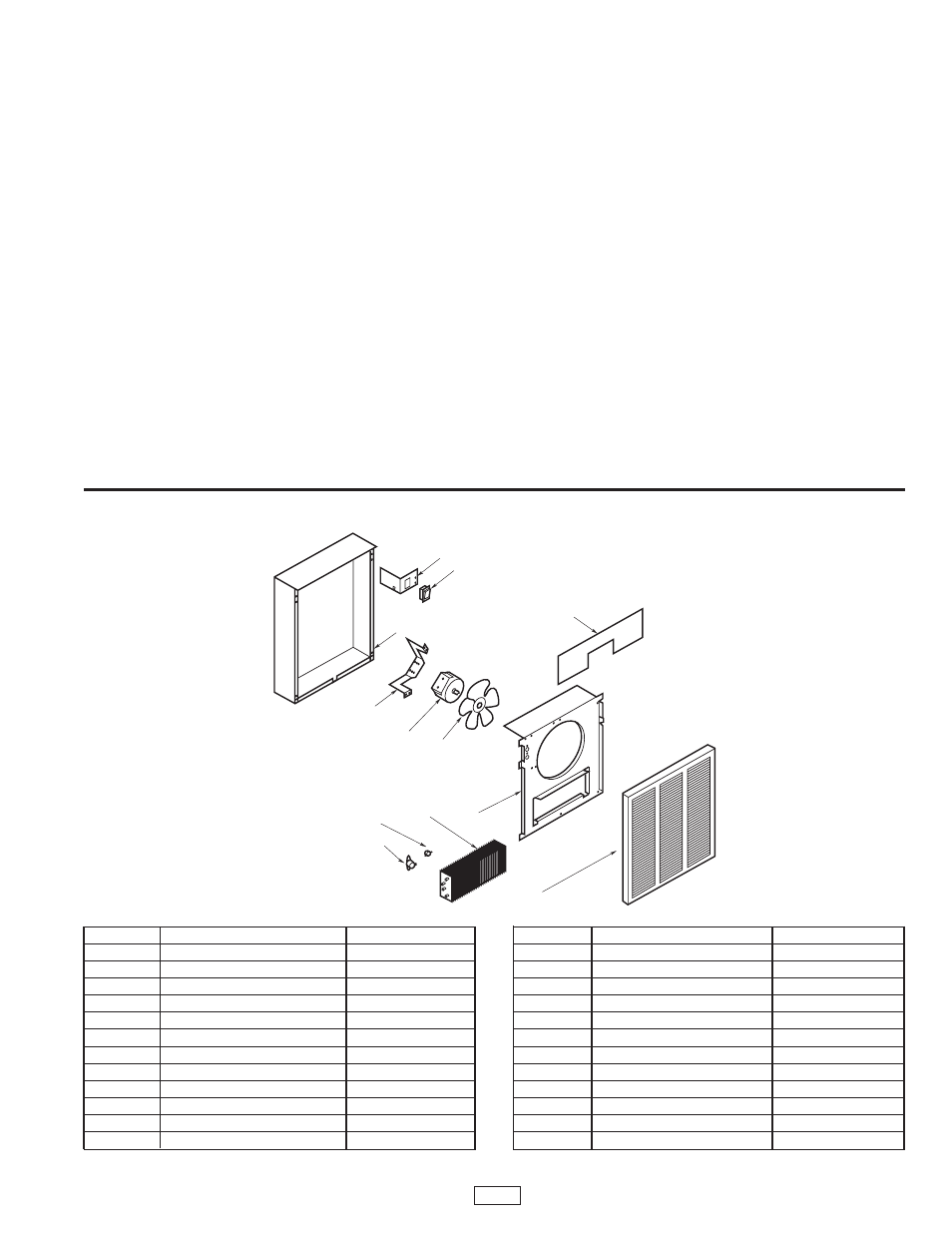
Ref. No.
Description
Part Number
1
Back Box
1203-2015-000
2
Front Cover
1402-2149-000
3
Motor, 208V
3900-2010-000
3
Motor, 240/277V
3900-2010-001
3
Motor, 120V
3900-2010-003
4
Fan Panel
4513-2042-000
5
Motor Mount
310914002
6
High Limit
410169001
7
Fan Delay
410074000
8
Disconnect Switch
410170001
9
Disconnect Switch Bracket
1215-2058-000
10
Element-1500W, 120V
302012827
Ref. No.
Description
Part Number
10
Element-1500W, 277V
302015006
10
Element- 2000W, 208V
302015001
10
Element- 2000W, 240V
302015002
10
Element- 2000W, 277V
302015003
10
Element- 3000W, 277V
302012006
10
Element- 4000W, 208V
302012007
10
Element- 4000W, 240V
302012008
10
Element- 4000W, 277V
302012009
10
Element- 4800W, 240V
302012010
10
Element- 4800W, 277V
302012011
11
Fan Blade
490030103
12
Wire Compartment Cover
4513-2037-000
NOTE: Always order by “Part Number”, never by “Ref. No.”
Renewal Part Indentificaiton
1
8
9
5
3
11
7
6
10
4
2
12
3