Caution, Heater checkout and operation, Maintenance and cleaning – Qmark CWH Series - Architectural Fan-Forced Wall Heaters User Manual
Page 3: Figure 3, Figure 4
3
3.
Insert wiring plug from heater/fan assembly into socket in back box.
4.
Fit heater/fan assembly into back box and secure in place with (2)
screws provided through the center slots in the fan assembly.
NOTE: Use the screws provided by the factory to install fan deck to the
back box.
INSTALLATION OF FRONT COVER (GRILLE) AND
THERMOSTAT KNOB
1.
Attach grille bracket with screw provided in the top part of
the back box as shown in Figure 4.
2.
Mount top portion of the grille over the grille bracket and
push down until grille is secure.
3.
Insert screw through bottom of grille louver to mounting hole
and tighten screw.
4.
Fit the thermostat knob on to the thermostat shaft and push
into place.
HEATER CHECKOUT AND OPERATION
1.
After heater is completely assembled, push the disconnect
switch to the “on” position and rotate thermostat knob coun-
terclockwise until control stops.
This is the minimum heat
setting.
2.
Turn power supply to heater “ON” at main switch panel.
3.
Heater should not operate. If it operates, disconnect power
and re-check wiring.
4.
Rotate thermostat clockwise until it stops (maximum heat
setting) and wait at least 2 minutes. Fan control will delay
fan coming on until element is warm.
5.
If heater and fan do not come on, disconnect power and
check wiring.
6.
Allow heater to continue to operate until room temperature
reaches desired comfort level. Then rotate thermostat knob
counterclockwise slowly until thermostat clicks off. Fan will
continue to operate for a minute or so until element cools.
7.
It may be necessary to readjust thermostat a time or so until
exact comfort level is attained.
Rotation in the clockwise
direction will increase the amount of time the heater will pro-
duce heat.
Rotation in the counterclockwise direction will
reduce the amount of time the heater is on.
NOTE: For best results, the heater should be left “ON” constantly during
the heating season as the thermostat, when properly set, will maintain the
desired temperature. In the full counter-clockwise position the heater will
remain off until the room temperature drops well below freezing.
MAINTENANCE AND CLEANING
Your heater is designed for years of trouble-free operation and requires no
special maintenance other than occasional cleaning. The motor is perma-
nently lubricated.
Once each year, the heater should be cleaned to remove dust and other
foreign material which has collected during the heating season, as follows:
1.
Turn power off at main switch.
2.
Remove thermostat knob and grille.
3.
Use vacuum cleaner with brush attachment to remove dust and dirt
that has accumulated in heater (especially around element and fan
blade). Do not use water or any cleaners to clean heater compo-
nents.
4.
Replace grille and thermostat knob.
5.
Wipe grille clean with a damp cloth. DO NOT use waxes or any
cleaners that leave a residue since these may discolor during heater
operation.
6.
Turn the main line switch on at the switch panel to restore power to
heater. The heater is now ready for another season of operation.
OPERATIONAL NOTICE
Your heater is equipped with an automatic reset high limit control that
will automatically turn the heater off to prevent a fire if the heater over-
heats. Should this occur, the indicator light will illuminate and will contin-
ue to shine until the limit resets.
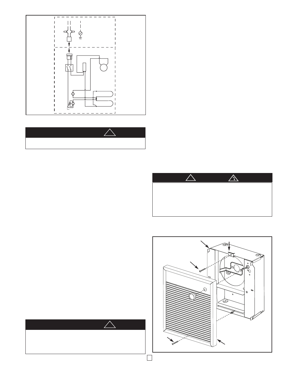
L1
L2(N)
*WHITE FOR 120 AND 277 VOLT
G
R
B
L
K
*B
L
K
BACK BOX
WIRING
B
L
U
E
B
L
U
E
B
L
A
C
K
B
L
A
C
K
DISCONNECT
SWITCH
INDICATOR
LIGHT
HIGH
LIMIT
FAN
DELAY
BOTTOM ELEMENT
TOP ELEMENT
THERMOSTAT
FAN MOTOR
HEATER ASSEMBLY
Figure 3
*
THE ILLUMINATED INDICATOR LIGHT SIGNIFIES THE HEATER
HAS BEEN SUBJECTED TO SOME ABNORMAL CONDITION.
CHECK HEATER TO INSURE THAT IT HAS NOT BEEN BLOCKED IN
ANY MANNER (IF SO, REMOVE BLOCKAGE).
IF THERE IS NO
INDICATION OF BLOCKAGE, IT IS RECOMMENDED THE HEATER
BE CHECKED BY A REPUTABLE ELECTRICIAN OR REPAIR SER-
VICE TO INSURE THE HEATER HAS NOT BEEN DAMAGED.
CAUTION
!
GRILLE BRACKET
SCREW
BACK BOX
SCREW
GRILLE
Figure 4
IF FAN SHUTS OFF IMMEDIATELY, THERMOSTAT WIRING IS
INCORRECT AND MUST BE CHANGED. FAN MUST DELAY SHUT-
TING OFF TO EXPEL RESIDUAL HEAT TO PREVENT PREMA-
TURE AGING OF INTERNAL HEATER COMPONENTS THAT
COULD LEAD TO A HAZARD OR PREMATURE FAILURE.
a
CAUTION
!
BE SURE ALL WIRING IS SECURELY ROUTED AWAY FROM FAN
AND ELEMENT.
a
CAUTION
!