Maintenance, Wiring, Warning – Qmark CRN - Industrial Permanent Infrared Heaters User Manual
Page 3
MAINTENANCE
The reflectors should be kept clean to obtain the maximum
radiant output.
Element Replacement
1. Remove Terminal Box Cover.
2. Disconnect lead wires from heater terminals and disengage
box from conduit /cable fitting.
3. Remove safety grills (if installed).
4. Loosen (2) 3/8” nuts from the terminal box bracket located on
the back of the heater and slide the entire heating element
assembly out of the reflector assembly.
5. Remove bulkhead fitting nut and washers.
6. Remove failed element and replace with a new element.
7. Place gasket on the bulkhead fitting and insert terminals and
fitting into the element hole in the terminal box.
8. Place washer and nut on the bulkhead fitting and tighten.
9. Reassemble by following the reverse procedures (steps 4
through 1)
WIRING
1. Use heater only at the voltage specified on the nameplate.
2. Branch circuit wire for connection to heater must be at least
90°C wire. Use copper conductors only.
3. The heater connection points are located in the gasketed
terminal enclosure. To remove cover, remove 4 screws on
the cover. Remove the cover to expose wiring connection
points.
4. A green ground terminal is provided in the bottom of the
enclosure. The ground wire should be connected before
other connections are made.
5. Refer to Table 1 for proper entrance wiring size.
6. Heater can be wired with rigid or flexible conduit.
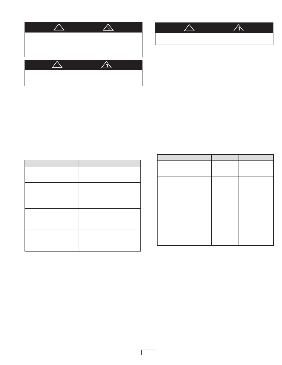
ELECTRIC SHOCK HAZARD. Disconnect all power before
installing or servicing heater. Failure to do so could result in
personal injury or property damage. Heater must be
effectively grounded in accordance with the National Electrical
Code, NFPA 70.
a
WARNING
All electrical wiring must be done by a qualified person in
accordance with National Electrical Code (NEC) and meet all
state and local regulations.
a
WARNING
Grill Kit Selection Guide
Model
Volts
Watts
Optional Grill Kit
N1011B
120
1000
N1081B
208
1000
NWG01
N1021B
240
1000
N1511B
120
1500
N1581B
208
1500
N1521B
240
1500
NWG105
N1571B
277
1500
N1531B
347
1500
N2001B
208
2000
N2021B
240
2000
NWG200
N2071B
277
2000
N2031B
347
2000
N2501B
208
2500
N2521B
240
2500
NWG250
N2571B
277
2500
N2531B
347
2500
ELECTRIC SHOCK HAZARD. Disconnect all power before
servicing or replacing heating elements.
a
WARNING
Replacement Parts
Model
Volts
Watts
Element
N1011B
120
1000
322-074905-143
N1081B
208
1000
322-074905-144
N1021B
240
1000
322-074905-145
N1511B
120
1500
322-074905-148
N1581B
208
1500
322-074905-149
N1521B
240
1500
322-074905-150
N1571B
277
1500
322-074905-151
N1531B
347
1500
322-074905-152
N2001B
208
2000
322-074905-153
N2021B
240
2000
322-074905-154
N2071B
277
2000
322-074905-155
N2031B
347
2000
322-074905-156
N2501B
208
2500
322-074905-157
N2521B
240
2500
322-074905-158
N2571B
277
2500
322-074905-159
N2531B
347
2500
322-074905-160
3
!
!
!
Hanging Kit for All Models: MHK