Figure 1-3, Table 1-2 – Cisco IP/TV 3400 Series User Manual
Page 32
Chapter 1 Introducing IP/TV Servers
Cisco IP/TV Broadcast Servers
1-6
Cisco IP/TV 3400 Series Servers User Guide
OL-4467-01
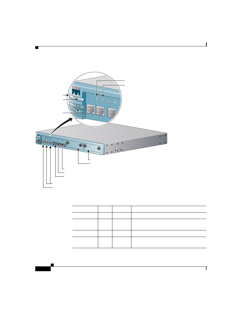
Figure 1-3
Cisco IP/TV 3425 and 3425A Broadcast Server LEDs
Table 1-2
Cisco IP/TV 3425 and 3425A Broadcast Server LEDs
Indicator
Color
State
Description
Power
Green
On
Power is flowing to the IP/TV Server.
System
Green
On
The network connection is active (packets
are being sent or received).
LINK
Green
On
IP/TV Server is connected to the network.
100 Mbps
Green
On
The connection is a 100BASE-TX (Fast
Ethernet) connection.
LINK
CONS
ETHERNET 0
ETHERNET 1
SCSI LVD ONL
Y
100Mbps
LINK 100Mbps
SLOT 0
SLOT 0
SLOT 1
SLOT 1
0 1 2 3
LINK
CONS
ETHERNET 0
ETHERNET 1
100Mbps
LINK 100Mbps
0 1 2 3
Ethernet ports
Console port
Slot 1 LED
Slot 0 LED
SCSI LVD only port
Slot 1
Slot 0
100Mbps LED
Link LED
Power indicator
System indicator
Status LEDs
43905