Replacing the display assembly – Dell Studio 1435 (Late 2008) User Manual
Page 17
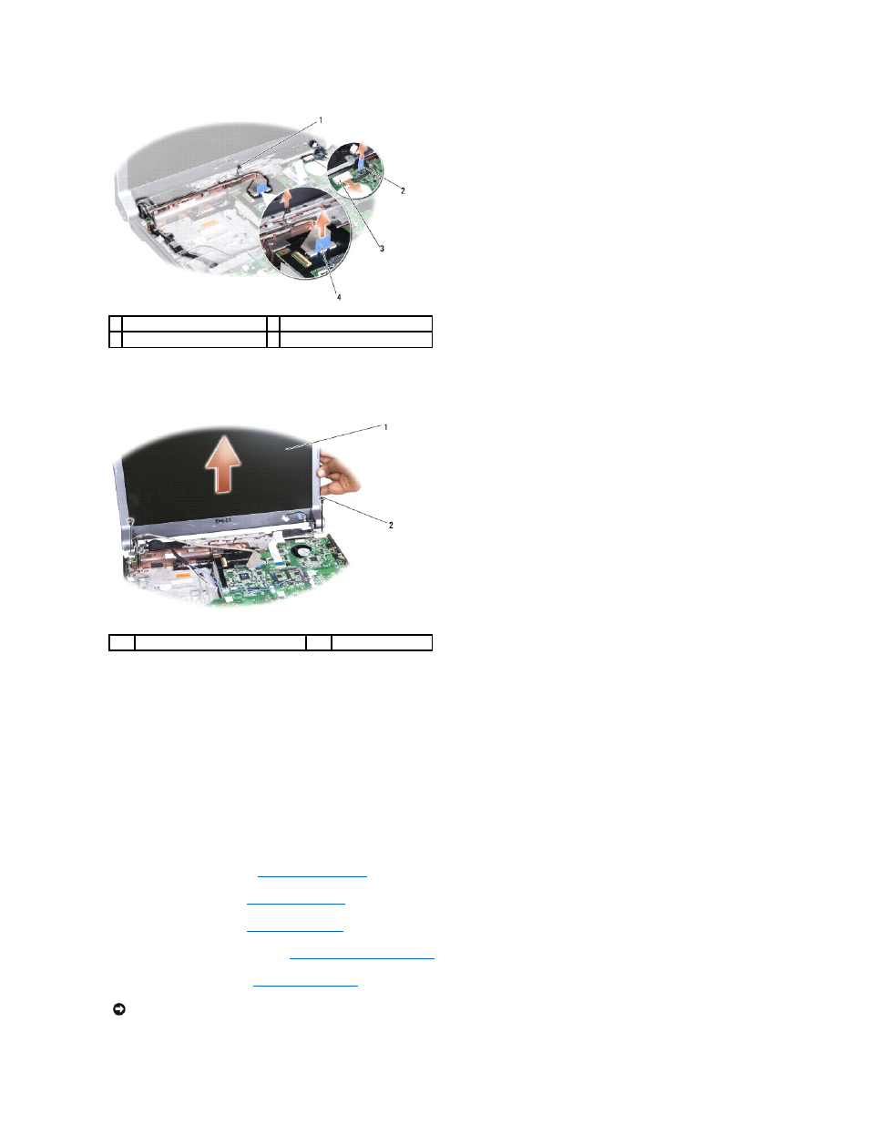
11.
Remove the two screws (one on each hinge).
12.
Remove the display assembly.
Replacing the Display Assembly
1.
Place the display assembly in position and replace the two screws.
2.
Route the camera cable (optional), power button cable, and display cable through the routing guides and connect the cables to the respective system
board connectors.
3.
Replace the screw that secures the display cable.
4.
Route the Mini-Card antenna cables through the routing guides.
5.
Replace the two screws at the base of the computer.
6.
Replace the optical drive (see
Replacing the Optical Drive
).
7.
Replace the palm rest (see
Replacing the Palm Rest
).
8.
Replace the keyboard (see
Replacing the Keyboard
).
9.
Replace the center control cover (see
Replacing the Center Control Cover
).
10.
Replace the base cover (see
Replacing the Base Cover
).
1 display cable screw
2 camera cable pull-tab (optional)
3 power button cable connector
4 display cable pull-tab
1
display assembly
2
screw (2)
NOTICE:
Before turning on the computer, replace all screws and ensure that no stray screws remain inside the computer. Failure to do so may result in
damage to the computer.