Dell Precision 420 User Manual
Page 70
Port designations are used, for example, in software installation procedures that include a step in which you identify the port to which your printer is
attached, thus telling your software where to send its output. (An incorrect designation prevents the printer from printing or causes scrambled print.)
Serial Port Connectors
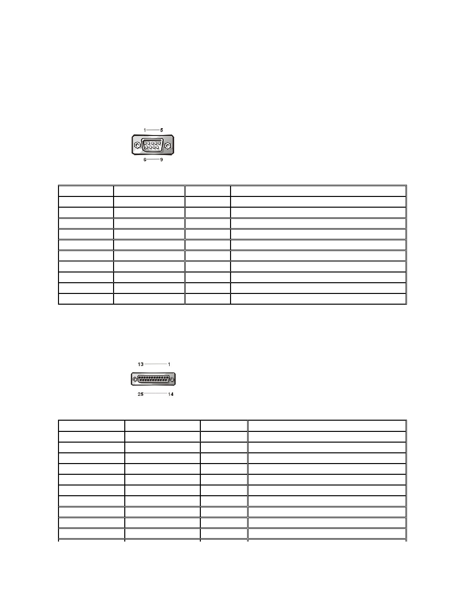
If you reconfigure your hardware, you may need pin number and signal information for the serial port connectors. Figure 4 illustrates the pin
numbers for the serial port connectors, and Table 3 lists and defines the pin assignments and interface signals for the serial port connectors.
Figure 4. Pin Numbers for the Serial Port Connectors
Table 3. Pin Assignments and Interface Signals for the Serial Port Connectors
Parallel Port Connector
If you reconfigure your hardware, you may need pin number and signal information for the parallel port connector. Figure 5 illustrates the pin
numbers for the parallel port connector, and Table 4 lists and defines the pin assignments and interface signals for the parallel port connector.
Figure 5. Pin Numbers for the Parallel Port Connector
Table 4. Pin Assignments and Interface Signals for the Parallel Port Connector
Pin
Signal
I/O
Definition
1
DCD
I
Data carrier detect
2
SIN
I
Serial input
3
SOUT
O
Serial output
4
DTR
O
Data terminal ready
5
GND
N/A
Signal ground
6
DSR
I
Data set ready
7
RTS
O
Request to send
8
CTS
I
Clear to send
9
RI
I
Ring indicator
Shell
N/A
N/A
Chassis ground
Pin
Signal
I/O
Definition
1
STB#
I/O
Strobe
2
PD0
I/O
Printer data bit 0
3
PD1
I/O
Printer data bit 1
4
PD2
I/O
Printer data bit 2
5
PD3
I/O
Printer data bit 3
6
PD4
I/O
Printer data bit 4
7
PD5
I/O
Printer data bit 5
8
PD6
I/O
Printer data bit 6
9
PD7
I/O
Printer data bit 7
10
ACK#
I
Acknowledge