Connecting drives, Connecting drives -3, Figure 7-3 – Dell OptiPlex G1 User Manual
Page 115: Rqqhfwlqj'ulyhv
Installing Drives
7-3
To remove the insert covering a 5.25-inch bay, follow these steps:
7XUQRIIWKHV\VWHPLQFOXGLQJDQ\DWWDFKHGSHULSKHUDOVDQGGLVFRQQHFW
DOOWKHDOWHUQDWLQJFXUUHQW$&SRZHUFDEOHVIURPWKHLUSRZHUVRXUFHV
5HPRYHWKHFRPSXWHUFRYHUDVLQVWUXFWHGLQ´5HPRYLQJWKH&RPSXWHU
&RYHUµLQ&KDSWHU
&$87,216HH´3URWHFWLQJ$JDLQVW(OHFWURVWDWLF'LVFKDUJHµLQWKHVDIHW\
LQVWUXFWLRQVDWWKHIURQWRIWKLVJXLGH
5HPRYHWKHIURQWEH]HODVLQVWUXFWHGLQWKHSUHYLRXVVHFWLRQ´5HPRY
LQJDQG5HSODFLQJWKH)URQW%H]HOµ
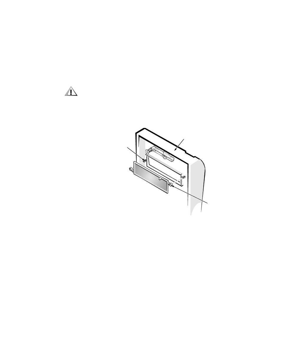
:LWK\RXUWKXPEVSUHVVLQHDFKHQGRIWKHLQVHUWXQWLOLWVQDSVIUHHRI
WKHEH]HOVHH)LJXUH
)LJXUH5HPRYLQJWKH)URQW3DQHO,QVHUWIRUD,QFK%D\
To replace a front-panel insert for a 5.25-inch bay, work from inside the bezel. Insert
the two ring-tabs (one on each end of the insert) over the posts on the inside of the
bay opening, and firmly press both ends of the insert into place (see Figure 7-3).
&RQQHFWLQJ'ULYHV
When installing a drive, you connect two cables—a direct current (DC) power cable
and an interface cable—to the back of the drive. Your drive’s power input connector
(to which you connect the DC power cable) resembles the connector shown in
Figure 7-4.
posts (2)
computer
cover
ring-tabs (2)