System board connectors, Able (see figure 6-2 for, E applicable (see figure 6-2 for connector – Dell PowerEdge 1900 User Manual
Page 127: E figure 6-2 for the locations of these connectors, And see figure 6-2 for the location of the, Int_storage). see figure 6-2 for th, Figure 6-2, Figure 6-2) and the other end to the connect, See figure 6-2 for the location of, Beneath the cooling shroud. see figure 6-2
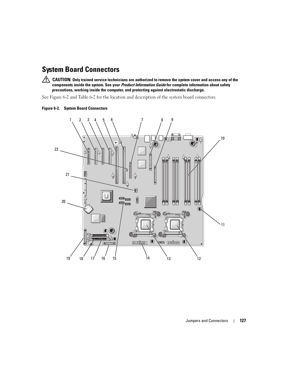 System board connectors, Able (see figure 6-2 for, E applicable (see figure 6-2 for connector | E figure 6-2 for the locations of these connectors, And see figure 6-2 for the location of the, Int_storage). see figure 6-2 for th, Figure 6-2, Figure 6-2) and the other end to the connect, See figure 6-2 for the location of, Beneath the cooling shroud. see figure 6-2 | Dell PowerEdge 1900 User Manual | Page 127 / 166
 See also other documents in the category Dell Computer hardware:
- PowerEdge RAID Controller H700 (56 pages)
- PowerEdge RAID Controller H700 (200 pages)
- PowerEdge RAID Controller H700 (178 pages)
- PowerVault 130T DLT (Tape Library) (49 pages)
- PowerVault TL2000 (1 page)
- PowerVault 110T DLT VS80 (Tape Drive) (49 pages)
- PowerVault TL2000 (22 pages)
- PowerVault TL4000 (306 pages)
- PowerVault TL2000 (2 pages)
- PowerVault TL4000 (2 pages)
- PowerVault TL2000 (176 pages)
- PowerVault TL2000 (16 pages)
- PowerVault TL2000 (3 pages)
- PowerVault TL2000 (116 pages)
- PowerEdge 800 (24 pages)
- PowerEdge 800 (82 pages)
- PowerEdge 800 (2 pages)
- PowerEdge 800 (27 pages)
- PowerEdge 800 (28 pages)
- PowerEdge 800 (58 pages)
- PowerEdge 800 (87 pages)
- PowerEdge 6400 (86 pages)
- PowerVault 124T (56 pages)
- PowerVault 124T (66 pages)
- PowerVault 124T (57 pages)
- PowerVault 110T LTO (Tape Drive) (28 pages)
- PowerVault 124T (55 pages)
- PowerVault 124T (73 pages)
- PowerVault 124T (65 pages)
- PowerVault 124T (4 pages)
- PowerVault 124T (79 pages)
- PowerVault 124T (2 pages)
- PowerVault 124T (64 pages)
- PowerVault TL4000 (16 pages)
- PowerVault TL4000 (116 pages)
- PowerVault TL4000 (1 page)
- PowerVault TL4000 (66 pages)
- PowerVault TL4000 (22 pages)
- PowerVault TL4000 (3 pages)
- PowerVault TL4000 (176 pages)
- PowerVault TL4000 (2 pages)
- PowerEdge RAID Controller 6i (120 pages)
- PowerEdge RAID Controller 6i (156 pages)
- PowerVault 715N (Rackmount NAS Appliance) (57 pages)
- PowerVault 715N (Rackmount NAS Appliance) (10 pages)