Cooling shrouds, Remove the cooling shrouds (see, Removing the pci cooling shroud – Dell PowerEdge 1500SC User Manual
Page 36: Replace the pci cooling shroud (see, Installing the pci cooling shroud
8.
Replace the PCI cooling shroud (see "
Installing the PCI Cooling Shroud
").
9.
Replace the right-side cover (see "
Removing the Side Covers
" in "Troubleshooting Your System").
Cooling Shrouds
Your system contains two cooling shrouds. The PCI cooling shroud covers the expansion cards and the microprocessor/memory module cooling shroud covers
the microprocessors and memory modules. This shroud is hinged in the middle to facilitate the removal and installation of the shroud.
Removing the PCI Cooling Shroud
1.
Turn off the system, including any attached peripherals, and disconnect the system from the electrical outlet.
2.
Remove the system's right-side cover (see "
Removing the Side Covers
" in "Troubleshooting Your System").
3.
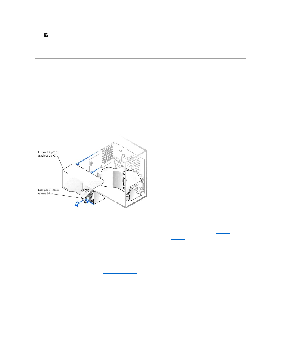
Use your index finger to pull the back-panel release tab and swing the cooling shroud up and out of the chassis (see
).
4.
Disconnect the PCI fan power cable from the system board (see
).
Figure 6-6. Removing and Installing the PCI Cooling Shroud
Installing the PCI Cooling Shroud
1.
Connect the PCI fan power cable to the system board.
2.
3.
Swing the cooling shroud down until it snaps into place securing the shroud to the system (see
).
4.
Replace the system's right-side cover.
5.
Replace the front bezel.
Removing the Microprocessor and Memory Module Cooling Shrouds
1.
Turn off the system, including any attached peripherals, and disconnect the system from the electrical outlet.
2.
Remove the system's right-side cover (see "
Removing the Side Covers
" in "Troubleshooting Your System").
3.
Press the release tab on the memory modules shroud and rotate the shroud until the tabs release from the slots in the microprocessor shroud (see
).
4.
Lift the memory modules shroud from the system.
5.
While pulling the release tab on the shroud that covers the microprocessors, lift the shroud upward so that the four retaining tabs that secure the
shroud to the back of the chassis can be pulled through the back panel (see
6.
Lift the microprocessor cooling shroud up and out of the chassis.
Figure 6-7. Removing and Installing the Microprocessor and Memory Module Cooling Shrouds
NOTE:
Installing a filler bracket over an empty expansion card slot is necessary to maintain Federal Communications Commission (FCC)
certification of the system. The brackets also keep dust and dirt out of the system and aid in proper cooling and airflow inside the system.