Installing system board options – Dell PowerEdge 1500SC User Manual
Page 32
Back to Contents Page
Installing System Board Options
Dell™ PowerEdge™ 1500SC Systems Installation and Troubleshooting Guide
Removing and Installing Power Supplies
This section describes how to install the following options:
l
Expansion cards
l
Memory upgrades
l
Microprocessor upgrades
This section also includes instructions for replacing the fan, cooling shrouds, power supplies, and system battery, if necessary.
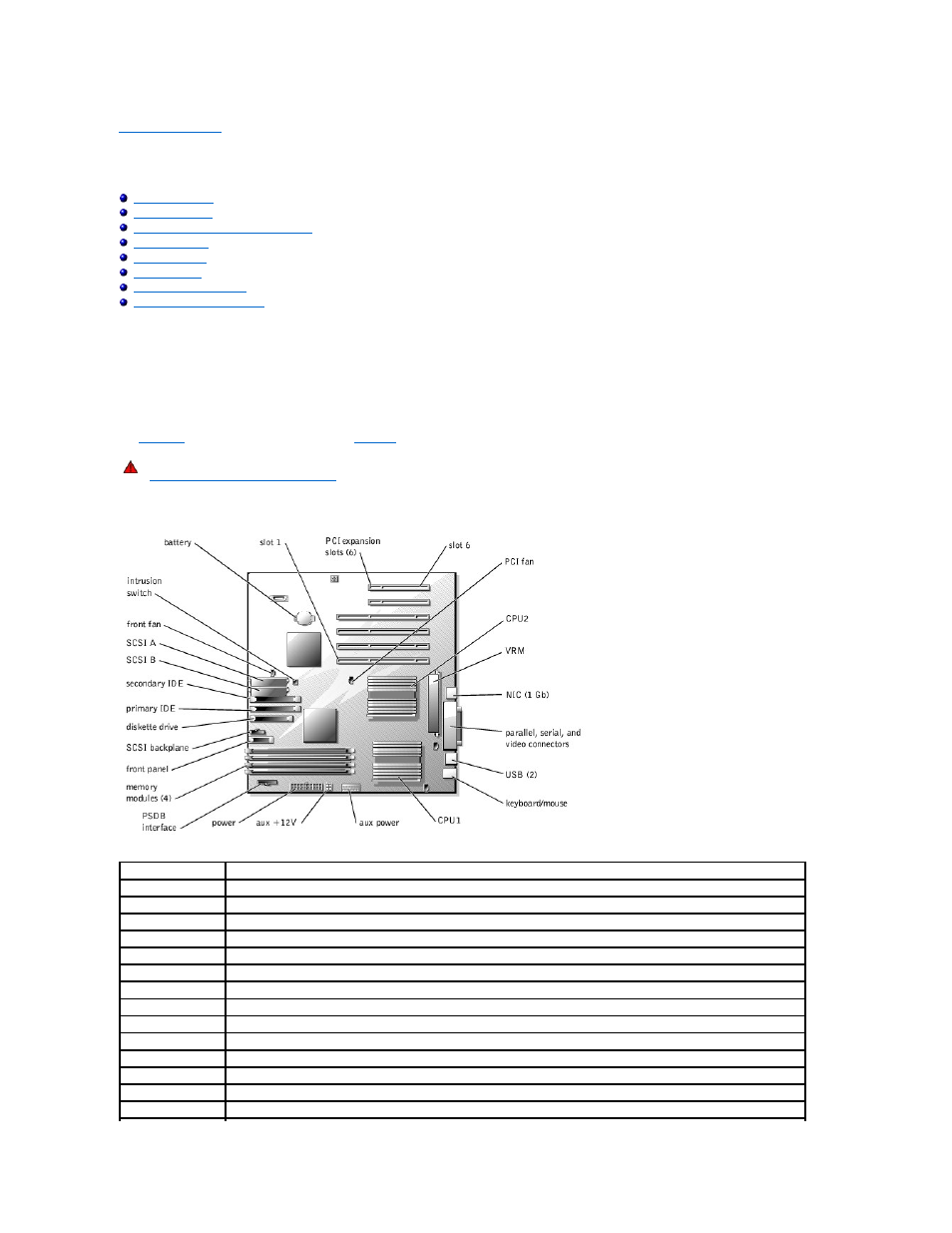
to locate the system board features.
describes the system board connectors and sockets.
Figure 6-1. System Board Connectors and Sockets
Table 6-1. System Board Connectors and Sockets
WARNING:
Before you perform this procedure, you must turn off the system and disconnect it from its power source. For more information, see
"
Safety First— For You and Your System
" in "Troubleshooting Your System."
Connector or Socket Description
SCSI BACKPLANE
Hot-pluggable SCSI backplane board interface cable connector
BATTERY
System battery connector
PARALLEL, COMn, VGA Parallel port connector; sometimes referred to as LPT1, serial port connectors; sometimes referred to as COM1, video connector
DIMM_n
Memory riser card connectors (2)
ENET_1GB
Ethernet connector
FAN
Power for the front system fan
SCSI_n
Power and data to the diskette and CD drive from the system board
PRIMARY IDE
CD drive connector
SECONDARY IDE
Tape drive connector
DISKETTE
Diskette connector
KYBD
Keyboard connector
MOUSE
Mouse connector
PSDB I/F
Power supply distribution board interface connector
CNTL PNL
System control panel connector