Autostore and power up recall, Software controlled store and recall cycle, Hardware store cycle – Cypress CY14E102L User Manual
Page 10
ADVANCE
CY14E102L, CY14E102N
Document Number: 001-45755 Rev. *A
Page 10 of 21
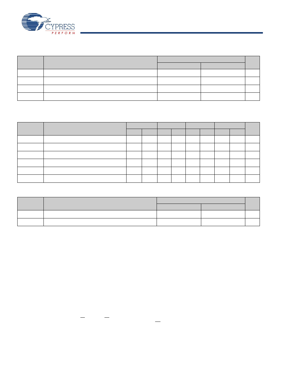
AutoStore and Power Up RECALL
Parameters
Description
CY14E102L/CY14E102N
Unit
Min
Max
t
HRECALL
Power Up RECALL Duration
20
ms
t
STORE
STORE Cycle Duration
15
ms
V
SWITCH
Low Voltage Trigger Level
4.4
V
t
VCCRISE
VCC Rise Time
150
μs
Software Controlled STORE and RECALL Cycle
The following table lists the software controlled STORE and RECALL cycle parameters.
Parameters
Description
15ns
20 ns
25ns
45ns
Unit
Min
Max
Min
Max
Min
Max
Min
Max
t
RC
STORE and RECALL Initiation Cycle Time
15
20
25
45
ns
t
AS
Address Setup Time
0
0
0
0
ns
t
CW
Clock Pulse Width
12
15
20
30
ns
t
GHAX
Address Hold Time
1
1
1
1
ns
t
RECALL
RECALL Duration
200
200
200
200
μs
t
SS
Soft Sequence Processing Time
70
70
70
70
μs
Hardware STORE Cycle
Parameters
Description
CY14E102L/CY14E102N
Unit
Min
Max
t
DELAY
Time allowed to complete SRAM cycle
1
70
μs
t
HLHX
Hardware STORE pulse width
15
ns
Notes
16. t
HRECALL
starts from the time V
CC
rises above V
SWITCH.
17. If an SRAM Write has not taken place since the last nonvolatile cycle, no STORE takes place.
18. The software sequence is clocked with CE controlled or OE controlled reads.
19. The six consecutive addresses must be read in the order listed in the mode selection table. WE must be HIGH during all six consecutive cycles.
20. This is the amount of time it takes to take action on a soft sequence command.Vcc power must remain HIGH to effectively register command.
21. Commands such as STORE and RECALL lock out IO until operation is complete which further increases this time. See the specific command
.
22. On a hardware STORE initiation, SRAM operation continues to be enabled for time t
DELAY
to allow read and write cycles to complete.