Cabletron Systems SEH-22 User Manual
Page 52
APPENDIX A: EPIM INFORMATION
A-8
SEH USER’S GUIDE
A.2.2
Single Mode Fiber Optic Cable Specifications
Table A-2 shows Single Mode Fiber Optic Cable specifications for the
EPIM-F3.
Attenuation
Test the fiber optic cable with a fiber optic attenuation test set adjusted for
an 1300 nm wavelength. This test verifies that the signal loss in a cable is
10.0 dB or less for any given single mode fiber optic link.
Fiber Optic Budget and Propagation Delay
Fiber optic budget is the combination of the optical loss due to the fiber
optic cable, in-line splices, and fiber optic connectors. When determining
the maximum fiber optic cable length, the fiber optic budget (total loss of
10.0 dB or less between stations) and total network propagation delay
must be considered before fiber optic cable runs are incorporated in any
network design.
Propagation delay is the amount of time it takes data to travel from the
sending device to the receiving device. Total propagation delay allowed
for the entire network must not exceed 25.6
µ
s in one direction (51.2
µ
s
round trip). If the total propagation delay between any two nodes on the
network exceeds 25.6
µ
s, use bridges.
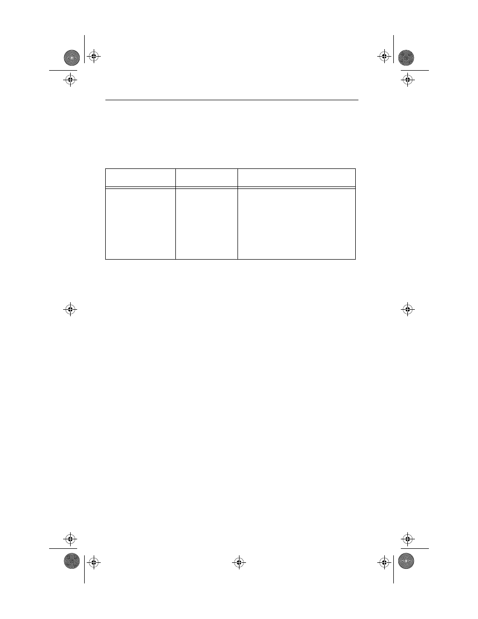
Table A-2. Single Mode Fiber Optic Cable Specifications
Cable Type
Attenuation
Maximum Cable Length
8/125-12/125
µ
m
10.0 dB or less
The maximum allowable fiber
optic cable length is 5 km (3.1
miles) with bridges at each seg-
ment end. However, IEEE
802.3 FOIRL specifications
specify a maximum of 1 km
(1093.6 yds).
SEH Book Page 8 Tuesday, March 19, 1996 4:12 PM