Caution, Warning – Carrier SEER 48ES User Manual
Page 20
20
NOTE: If the problem causing the inaccurate readings is a
refrigerant leak, refer to the Check for Refrigerant Leaks section.
Indoor Airflow and Airflow Adjustments
UNIT OPERATION HAZARD
Failure to follow this caution may result in unit damage.
For cooling operation, the recommended airflow is 350 to
450 cfm for each 12,000 Btuh of rated cooling capacity. For
heating operation, the airflow must produce a temperature
rise that falls within the range stamped on the unit rating
plate.
CAUTION
!
NOTE: Be sure that all supply--and return--air grilles are open,
free from obstructions, and adjusted properly. Airflow can be
changed using the User Interface.
ELECTRICAL SHOCK HAZARD
Failure to follow this warning could result in personal
injury or death.
Disconnect electrical power to the unit and install lockout
tag before changing blower speed.
!
WARNING
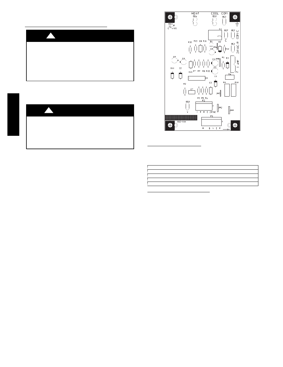
There are independent fan speeds for heating and cooling marked
“HEAT” and “COOL” on the interface fan board (IFB) (See Fig.
18). The unit is factory--shipped with heating and cooling speeds
noted in Table 9. There are 3 additional speed tap wires available
for use in either heating or cooling (For color coding on the indoor
fan motor leads, see Table 6). The additional 3 speed tap wires are
shipped loose with vinyl caps and are located in the control box,
near the interface fan board (IFB).
To change heating speed, remove the vinyl cap off of the desired
speed tap wire (Refer to Table 6 for color coding). Remove the
current speed tap wire from the “HEAT” terminal on the interface
fan board (IFB) (see Fig. 18) and place vinyl cap over the
connector on the wire. Connect the desired speed tap wire to the
“HEAT” terminal on the IFB. Table 9 shows the temperature rise
associated with each fan speed for a given static pressure. Make
sure that the speed chosen delivers a temperature rise within the
rise range listed on the unit rating plate.
To change cooling speed, remove the vinyl cap off of the desired
speed tap wire (Refer to Table 6 for color coding). Remove the
current speed tap wire from the “COOL” terminal on the interface
fan board (IFB) (see Fig. 18) and place vinyl cap over the
connector on the wire. Connect the desired speed tap wire to the
“COOL” terminal IFB. For optimum performance, add the wet coil
pressure drop in Table 10 to the system static to determine the
correct cooling airflow speed in Table 9 that will deliver the
nominal cooling airflow as listed in Table 1 for each size.
NOTE: For cooling operation, the recommended airflow is 350 to
450 CFM for each 12,000 Btuh of rated cooling capacity.
A07793
Fig. 18 -- Interface Fan Board (IFB)
Continuous Fan Operation
The continuous fan operates at the same fan speed as cooling
operation.
Table 6 – Color Coding for Indoor Fan Motor Leads
Black = High Speed
Orange = Med--- High Speed
Red = Med Speed
Pink = Med--- Low Speed
Blue = Low Speed
Cooling Sequence of Operation
With the room thermostat SYSTEM switch in the COOL position
and the FAN switch in the AUTO position, the cooling sequence
of operation is as follows:
1. When the room temperature rises to a point that is slightly
above the cooling control setting of the thermostat, the
thermostat completes the circuit between thermostat
terminal R to terminals Y and G.
2. The normally open contacts of energized contactor (C) close
and complete the circuit through compressor motor
(COMP) to condenser (outdoor) fan motor (OFM). Both
motors start instantly.
3. The set of normally open contacts of energized relay BM
close and complete the circuit through evaporator blower
(indoor) fan motor (IFM).
NOTE: Once the compressor has started and then stopped, it
should not be started again until 5 minutes have elapsed. The
cooling cycle remains on until the room temperature drops to a
point that is slightly below the cooling control setting of the room
thermostat. At this point, the thermostat breaks the circuit between
thermostat terminal R to terminals Y and G. These open circuits
deenergize contactor coil C. The condenser and compressor motors
stop. After a 60--sec. delay, the blower motor stops. The unit is in a
standby condition, waiting for the next call for cooling from the
room thermostat.
48E
S