Switching waveforms, Figure 10. read cycle timing – Cypress Perform CY7C1380F User Manual
Page 23
CY7C1380D, CY7C1382D
CY7C1380F, CY7C1382F
Document #: 38-05543 Rev. *F
Page 23 of 34
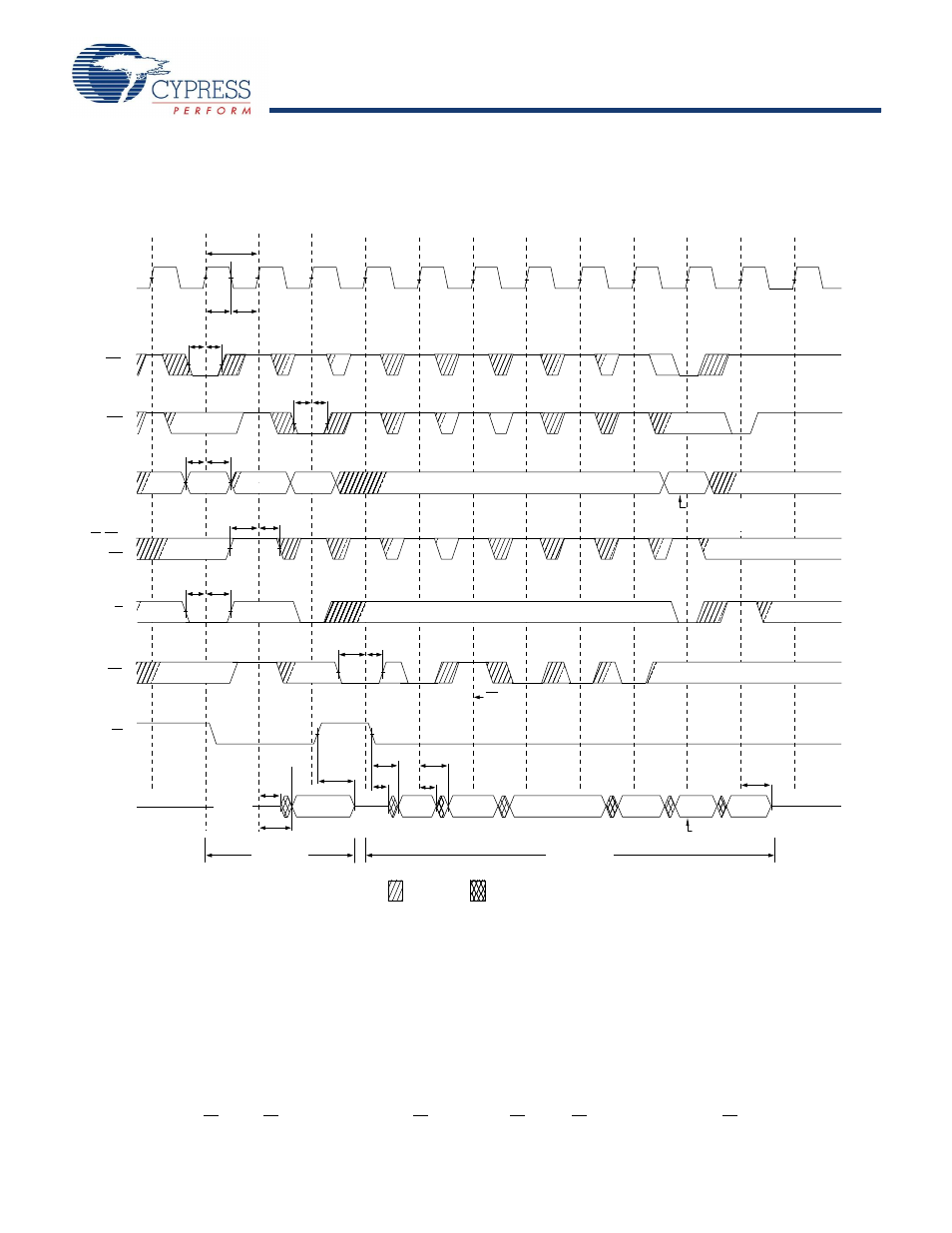
Switching Waveforms
Figure 10. Read Cycle Timing
tCYC
t
CL
CLK
ADSP
t
ADH
t
ADS
ADDRESS
t
CH
OE
ADSC
CE
tAH
tAS
A1
tCEH
tCES
GW, BWE,
BWx
Data Out (Q)
High-Z
tCLZ
tDOH
tCO
ADV
tOEHZ
tCO
Single READ
BURST READ
tOEV
tOELZ
tCHZ
ADV
suspends
burst.
Burst wraps around
to its initial state
tADVH
tADVS
tWEH
tWES
tADH
tADS
Q(A2)
Q(A2 + 1)
Q(A2 + 2)
Q(A1)
Q(A2)
Q(A2 + 1)
Q(A2 + 3)
A2
A3
Deselect
cycle
Burst continued with
new base address
DON’T CARE
UNDEFINED
Note
26. On this diagram, when CE is LOW: CE
1
is LOW, CE
2
is HIGH and CE
3
is LOW. When CE is HIGH: CE
1
is HIGH or CE
2
is LOW or CE
3
is HIGH.
This manual is related to the following products: