2 facilities, P.i.p, Jd c e g – Crown Audio IQ P.I.P.-DSP User Manual
Page 8
Page 8
IQ–P.I.P.–DSP Programmable Input Processor with DSP for IQ Systems
Reference Manual
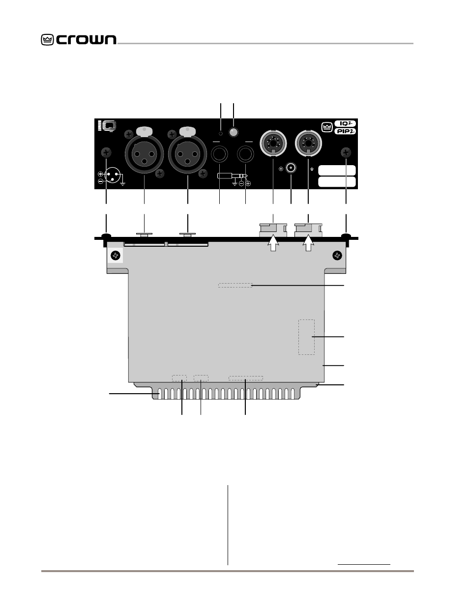
Fig. 2.1 The IQ–P.I.P.–DSP Facilities
Front View
Bottom View
P.I.P.
-DSP
PUSH
PUSH
DSPI
CH-2
CH-1
EXT. POWER INPUT
24 VDC / 400 mA
TIP =
RING =
IN
OUT
CROWN
BUS
AUDIO OUT
3
2
1
GND
C H - 2
C H - 1
AUDIO IN
DSP#.###
N
B
B
C
F
H
A
A
M
L
I
SW1
JP4
JP5
CH1
CH2
J
J
D
C
E
G
AVOID STATIC DAMAGE!
GROUND YOURSELF TO THE OUTER
METAL COLLAR OF ONE OF THE
CROWN BUS CONNECTORS.
RN1
RN2
K
K
2 Facilities
A. Mounting Screws
The
IQ–P.I.P.–DSP is secured to the back panel of the
amplifier with two phillips-head screws and star-tooth
lock washers. The lock washers are required for proper
ground connection.
B. Balanced Audio Inputs
A 3-pin female XLR connector is provided for balanced
audio input to each channel of the amplifier. Pin 1 is
ground (gnd); pin 2 is not inverted (+); and pin 3 is
inverted (–).
Do not use the Ch.2 input if the amplifier is
configured in either Bridge or Parallel-Mono mode.
C. Balanced Audio Outputs
A balanced phone jack is provided at the output of
each channel for “daisy chain” connection to other
components. Either balanced (tip, ring, sleeve) or un-
balanced (tip, sleeve) wiring may be used. The audio
signal feeding these outputs is post-processed.