Iq–p.i.p.–dsp, 2 prepare the amplifier, 3 install the – Crown Audio IQ P.I.P.-DSP User Manual
Page 11: Into the amplifier, 4 install the wiring
Page 11
IQ–P.I.P.–DSP Programmable Input Processor with DSP for IQ Systems
Reference Manual
settings for all 250 addresses.
2.
Set the jumpers JP4 and JP5.
If the
IQ–P.I.P.–
DSP is being installed into a PIP2-compatible or
Macro-Tech 5000VZ amplifier, move both
jumper JP4 and JP5 on the IQ circuit board to
the “OUT” position (Figures 2.1 and 3.6). Set
both JP4 and JP5 to the “IN” position for all other
amplifiers.
3.2 Prepare the Amplifier
3.
Turn down the level controls
(full counter-
clockwise) and
turn off the amplifier
.
4.
Disconnect the amplifier’s power cord.
5.
Remove the existing
P.I.P.
or cover panel from the
amplifier back panel (two screws). For
PIP2 amplifi-
ers this may involve disconnecting the
P.I.P. from a
PIP2 input adapter (Figure 3.4). If a PIP2 input
adapter is already present, do not remove the rib-
bon cables from the adapter. Otherwise you will
have to reconnect them in Step 9.
6.
Set the amplifier input sensitivity to 0.775 V.
(See the amplifier’s
Reference Manual.)
3.3 Install the
IQ–P.I.P.–DSP
into the
Amplifier
7.
Carefully ground yourself
to the chassis of the
amplifier before installing the
IQ–P.I.P.–DSP. It is
a good idea to maintain ground contact be-
tween yourself and the amplifier while inserting
the module into the
P.I.P. card rails (standard
P.I.P.-compatible amplifiers) or the PIP2 connec-
tor (
PIP2-compatible amplifiers).
8.
Install the
IQ–P.I.P.–DSP into the amplifier:
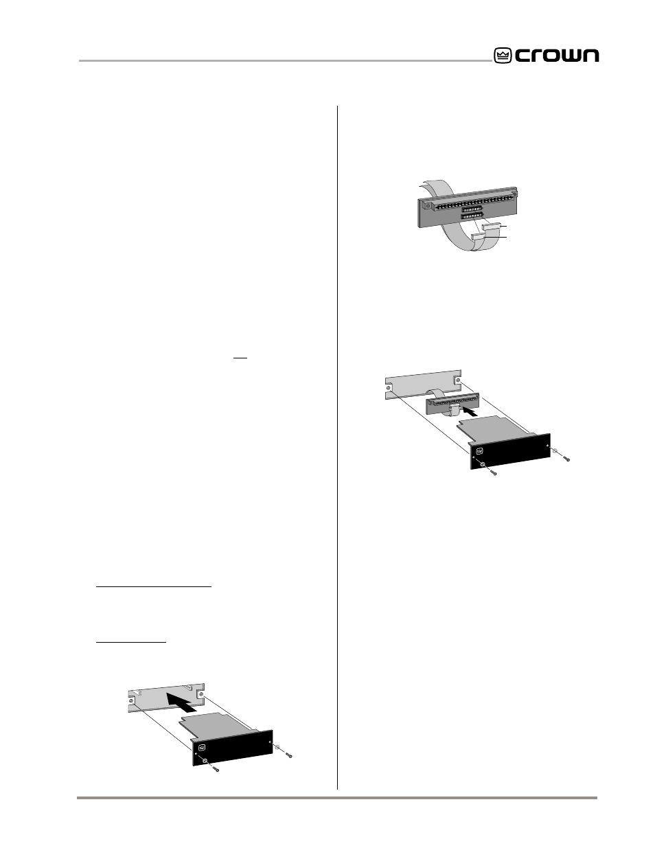
Standard P.I.P. Amplifiers: Align the edges of the
IQ–P.I.P.–DSP in the P.I.P. card rails and firmly
push the unit in until it is seated against the
mounting bracket (see Figure 3.3).
PIP2 Amplifiers: Connect the PIP2 input adapter
to the two input cables of the amplifier (Figure
Fig. 3.3 Installation into a Standard P.I.P. Amplifier
P.I.P.
MODULE
BACK PANEL
OF AMPLIFIER
Fig. 3.5 Installation into a PIP2 Amplifier
P.I.P.
MODU
LE
BACK PANEL
OF PIP2
AMPLIFIER
PIP2 ADAPTER
3.4). Notice that the
PIP2 input adapter should
be positioned with the
P.I.P. edge connector on
top facing away from the amplifier. The 20 pin
cable (A) is connected first then the 18 pin cable
and insert the assembly into the
P.I.P. opening in
the back of the amplifier.
9.
Tighten the two
P.I.P. mounting screws
until
the
P.I.P. is secured to the amplifier back panel.
3.4 Install the Wiring
10.
Connect the
IQ–P.I.P.–DSP to the IQ System
via the Crown Bus.
See Section 3.6 for full in-
structions.
11.
Connect the audio signal wiring
to the
IQ–
P.I.P.–DSP. This includes the XLR input wiring
and, if desired, the phone jack daisy chain wir-
ing. See Section 3.7 for full instructions.
Note:
The supplied EMI suppression core must be
used on the daisy chain outputs for the IQ–P.I.P.–
DSP to comply with FCC and EC EMC regula-
tions (see Section 3.7).
12.
Connect the amplifier back to the AC recep-
tacle.
Note: The IQ–P.I.P.–DSP may require an
external power supply in some amplifiers. See
A
B
B
A
18 PIN (B)
20 PIN (A)
PIP2 ADAPTER
FROM AMPLIFIER
Fig. 3.4 PIP2 Input Adapter Connection
(B) is connected. Both ribbon cables should ex-
tend below the
PIP2 input adapter.
Next, insert the edge connector of the
IQ–P.I.P.–
DSP into the PIP2 input adapter (see Figure 3.5)