Bottom, 3 installation, Iq–p.i.p.–dsp – Crown Audio IQ P.I.P.-DSP User Manual
Page 10: 1 prepare the
Page 10
IQ–P.I.P.–DSP Programmable Input Processor with DSP for IQ Systems
Reference Manual
3 Installation
Before beginning, please carefully note:
CAUTION: STATIC ELECTRICITY MAY DAMAGE
THE
IQ–P.I.P.–DSP MODULE.
Use caution when
handling the unit. Carefully ground yourself BEFORE
touching the
IQ–P.I.P.–DSP module. For added safety,
touch the outer metal collar of either Crown Bus
connector (see Figure 2.1). This should safely
discharge any static electricity through the ground
plane of the module. Avoid unnecessarily touching the
components, edge connector or solder pads on the
circuit boards.
NOTE — Amplifier Compatibility
The version of the
IQ-P.I.P.-DSP card you received will
vary depending on whether you indicated the card will
be installed on a PIP2-compatible amplifier (such as
the Crown MA-5000VZ or CT-10 Series amplifiers). The
correct card to install in a PIP2-compatible amplifier is
the
IQ-P.I.P.-DSP-PIP2. The standard IQ-P.I.P.-DSP
should be ordered for non-PIP2-compatible amplifiers.
Should you later wish to change the amplifier you are
using for your
IQ-P.I.P.-DSP installation, it is possible to
alter the card's configuration by simply removing or
installing two SIPS from the card’s circuit boards
1
. For
instructions on installing or removing these SIPS,
contact Crown Technical Support.
3.1 Prepare the
IQ–P.I.P.–DSP
1.
Set the IQ address switch SW1.
By giving each
IQ component a unique address, it can be individu-
ally controlled and monitored. Whenever the
IQ
System wants to send a command to just one IQ
component, it first sends its address and then the
is used to set the IQ address of the
IQ–P.I.P.–
DSP. No two IQ components of the same type
which are connected to the same Crown Bus
can have the same address. Suppose, for ex-
ample, an
IQ System has two Crown Bus loops,
1 and 2, and this
IQ–P.I.P.–DSP is to be installed
into loop 1 and given an address of 77. No other
IQ–P.I.P.–DSP can be given the same address in
loop 1. However, an
IQ–P.I.P.–DSP in loop 2 can
have the same address.
Different IQ components in the same Crown Bus
loop can have the same address. For example,
both an
SMX-6 mixer and an IQ–P.I.P.–DSP can
use address 77 in the same loop.
A valid IQ address is any number from 1 to 250.
Do not use a number higher than 250 since they
are reserved for special use. An address of “0”
(zero) should never be used except to put the
IQ–P.I.P.–DSP into a stand-alone mode where it
is invisible to the
IQ System and acts as a
BOTTOM
SW1
P.I.
P.-DSP
PUSH
PUSH
DSPI
CH-2
CH-1
EXT
. PO
WER
INP
UT
24 V
DC / 4
00 m
A
TIP
=
RIN
G =
IN
OUT
CROWN
BUS
AUD
IO O
UT
3
2
1
GND
C H -
2
C H -
1
AUDIO IN
DSP#.###
Fig. 3.1 IQ Address Switch (SW1) Location
command down the Crown Bus.
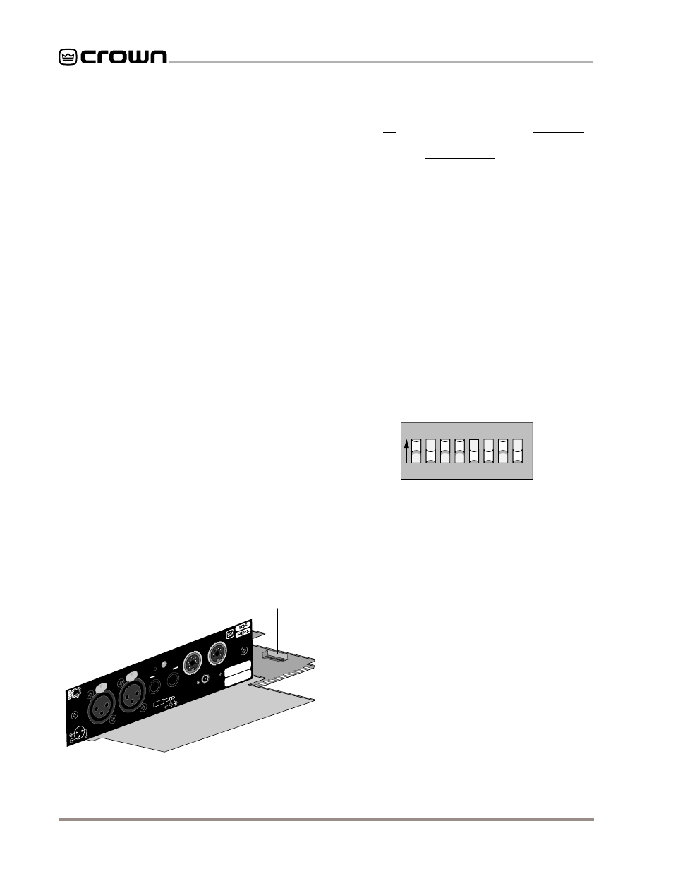
The 8-segment DIP switch (SW1) shown above
1
2
4
8
16
32
64
12
8
VALUE
TOP VIEW
1 2 3 4 5 6 7 8
ON
SW1
Fig. 3.2 IQ Address Switch (SW1) Values
“dumb” balanced audio input.
Switch SW1 is located on the right side on the
underside of the top circuit board (Figure 3.1). It
has eight segments because it actually contains
eight tiny switches inside. There is an arrow
printed on the switch along its left side that
points to the “ON” position and the switches are
numbered along the bottom (Figure 3.2).
Each of the eight switches in SW1 has a value
which doubles as the switch number increases.
For example switch 1 has a value of 1; switch 2
has a value of 2; switch 3 has a value of 4; switch
4 has a value of 8 and so on.
The address is determined by adding the values
of all “ON” switches. In Figure 3.2 switches 1, 3,
4 and 7 are on. Simply add the values to find the
address: 1+4+8+64=77.
A convenient series of IQ address tables are in-
cluded in Section 7. The tables show the switch
1
IQ-P.I.P.-DSP-PIP2 has SIPS installed; IQ-P.I.P.-DSP has SIPS removed.