5 technical information, 1 audio signals, 1 hardware processing – Crown Audio IQ P.I.P.-DSP User Manual
Page 21: Iq system, P.i.p, 2 signal flow processing, Odep
Page 21
IQ–P.I.P.–DSP Programmable Input Processor with DSP for IQ Systems
Reference Manual
5 Technical Information
The purpose of the
IQ–P.I.P.–DSP is to provide
extensive signal processing capabilities and to enable
an
IQ System to control and monitor a P.I.P.-compatible
amplifier. See Sections 2 and 3 for a list of the facilities
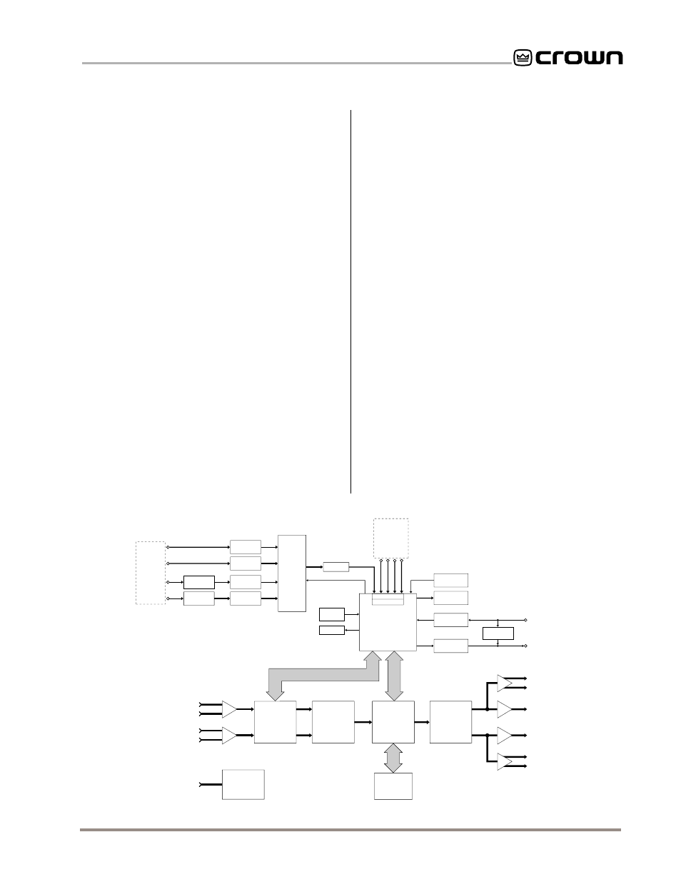
and features. Figures 5.1 and 5.2 show hardware and
signal flow block diagrams of the unit.
5.1 Audio Signals
5.1.1 Hardware Processing
(see Figure 5.1)
Balanced and unbalanced audio signals enter the mod-
ule at the XLR connectors. From these connectors, the
signals are RFI filtered and fed into a balanced to single-
ended conversion stage. Then they are sent to a monitor
input (discussed below) and also to a DCA (Digitally Con-
trolled Attenuator) for gain ranging via the
IQ System
. This
is essential because the DSP (Digital Signal Processing)
system has limited voltage headroom.
After the DCA, both channels are sent to an 18-bit dual-
channel ADC (Analog to Digital Converter). The ADC pro-
vides brick-wall low-pass filtering and “volts to bits”
conversion. The output of the ADC is a multiplexed serial
bitstream which is sent to the DSP. The DSP operates on
each sample of both channels (one at a time) via machine
language program instructions (firmware). The output of
the DSP is a serial bitstream which is sent to the DAC
(Digital to Analog Converter). The DAC is an 18-bit dual-
channel device which demultiplexes Channel 1 and 2 and
converts the bits to volts. The DAC also provides low-pass
filtering. The output of the DAC drives the amplifier inputs
via the
P.I.P.
edge card connector as well as the “daisy
chain” outputs.
5.1.2 Signal Flow Processing
(see Figure 5.2)
The audio signals are attenuated via the input attenua-
tors, providing system gain setting as well as gain rang-
ing for the DSP system. The input compressor/limiters
then allow dynamic scaling of signals for many applica-
tions via common parameters such as threshold, ratio,
etc. The
ODEP
conservation limiters then provide system
protection with dynamic (but slowly varying) gain scaling
based on thermal conditions within the amplifier. Next the
signals are fed to the input protection limiters to keep the
signal below the voltage headroom of the DSP system.
The signal is then fed into eight cascaded fully program-
mable 2nd-order DSP filter cells. All filter cells are IIR
based to provide a proper magnitude/phase relationship
for crossover and equalization applications. Each filter cell
is controllable. 1st and 2nd-order filter types use one filter
cell. 3rd and 4th-order filter types use two filter cells. The
output of the filter block is sent to an adjustable digital
signal delay section for audio signal delay. The minimum
delay is hardware-limited to 1.25 milliseconds. The output
of the delay section is sent to the output limiter section.
The DSP output limiter dynamically adjusts the system
gain to explicitly limit the output voltage of the amplifier
within ½ dB by utilizing the output voltage monitor infor-
mation from the data acquisition system. Common limiter
Fig. 5.1 IQ–P.I.P.–DSP Hardware Circuit Block Diagram
MICROCONTROLLER
AUDIO
MONITOR
MULTI-
PLEXER
CROWN BUS
SERIAL
DATA INPUT
CROWN BUS
SERIAL
DATA OUTPUT
FUTURE HDWR
IOC
Vcc
ODEP
STATUS
MONITOR INPUTS
INPUT MUX
A/D CONV.
DSPI
EXTERNAL
RESET
AMP REMOTE
STANDBY
IQ ADDRESS
SWITCH
ISO. INPUT
RECEIVER
OUTPUT
DRIVER
DROP-OUT
RELAY
LOG AMP
PEAK
DETECTOR
PEAK
DETECTOR
PEAK
DETECTOR
PEAK
DETECTOR
CH 1
CH 2
CH 1
CH 2
AUDIO
INPUTS
AMPLIFIER
OUTPUTS
AUDIO
MONITOR
INPUTS
CH 1
CH 2
BALANCED AUDIO INPUTS
CH 1
CH 2
TO AMPLIFIER
AUDIO INPUTS
SWITCHABLE
INPUT PAD
SWITCHABLE
INPUT PAD
DIGITALLY
CONTROLLED
2-CHANNEL
ATTENUATOR
ANALOG TO
DIGITAL
CONVERTER
DIGITAL
SIGNAL
PROCESSOR
DIGITAL TO
ANALOG
CONVERTER
BALANCED
DAISY-CHAIN
OUTPUT
BALANCED
DAISY-CHAIN
OUTPUT
P.I.P.
POWER
SUPPLY
EXTERNAL POWER
SUPPLY INPUT
EXTERNAL
MEMORY