Crown Audio IQ P.I.P.-DSP User Manual
Page 13
Page 13
IQ–P.I.P.–DSP Programmable Input Processor with DSP for IQ Systems
Reference Manual
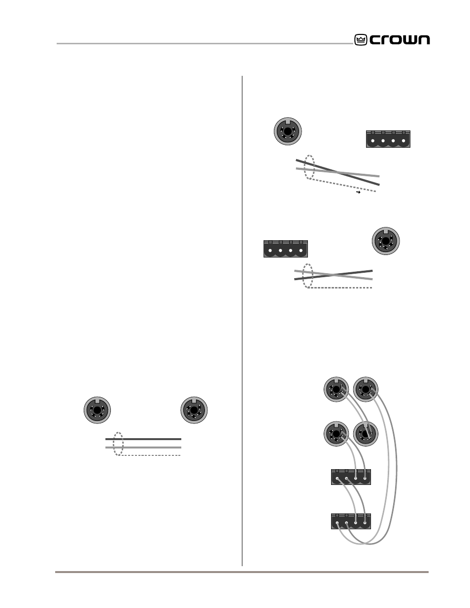
1 Input (–)
2 Input (+)
3 GND
4 Not used
5 Not used
IQ Component Input
2
5
3
4
1
Optional Shield
GND 1
Output (+) 2
Not used 3
Not used 4
IQ–P.I.P.–DSP Output
2
3
4
1
Figure 3.7 IQ–P.I.P.–DSP Output Connection
to Another IQ Component with DIN Connectors
OUT
IN
+ – + –
Output (+)
Output (–)
Input (+)
Input (–)
GND 1
Output (+) 2
Not used 3
Not used 4
IQ Mixer
2
3
4
1
Optional Shield
IQ–P.I.P.–DSP Output
OUT
IN
+ – + –
1 Input (–)
2 Input (+)
3 GND
4 Not used
5 Not used
Output (+)
Output (–)
Input (+)
Input (–)
IQ Mixer
2
5
3
4
1
Optional Shield
IQ–P.I.P.–DSP Input
Figure 3.9 An IQ Component with Screw Terminal
Plug Connected to the IQ–P.I.P.–DSP Input
Figure 3.8 IQ–P.I.P.–DSP Output Connection to an
IQ Component with a Screw Terminal Plug Connector
IQ Interface
IQ Component
IQ Component
IQ Component
CROWN BUS LOOP
Fig. 3.10 Crown Bus Wiring “Loops” from the
Output to the Input of Each IQ Component
than 1,000 feet (305 m)—or when required by
high-capacitance wire. Although we recommend
adding a repeater for loops longer than 1,000 feet,
it is often possible to go 2,000 feet (610 m) or
more. The most significant characteristic of the
wire is its capacitance. The lower the capaci-
tance, the longer the loop can be. Unshielded
wire typically has less capacitance.
•
Never use the ground wire in a mic snake line.
It may sometimes be convenient to run Crown Bus
data signals to and from stage monitor amplifiers
along unused wire pairs in a mic snake. If this is
done, do not use the ground wire which is nor-
mally connected to pin 1 on an XLR connector or
data noise will be added to the audio lines. Use
only the signal lines which normally connect to
pins 2 and 3 of the XLRs. The maximum possible
Crown Bus loop distance will be less because
typical mic cables have high capacitance.
Outside RF interference is seldom a problem for a
Crown Bus loop—especially if shielded twisted-pair
wire is used. However, there are extreme situations
when fiber optic wiring is recommended. For example,
locating a Crown Bus loop next to an AM radio
transmission line may require fiber optic cabling. An
extremely long Crown Bus loop distance may also
require fiber optic cabling.
There are two different types of connectors used for
Crown Bus wiring: DIN connectors and screw terminal
plugs. The
IQ–P.I.P.–DSP uses a 5-pin DIN connector
for input and a 4-pin DIN connector for output. Figure
3.7 shows how they should be wired.
The next two figures show how to connect the
IQ–
P.I.P.–DSP to other IQ components with different
connectors. Figure 3.8 shows how the Crown Bus
output of the
IQ–P.I.P.–DSP should be connected to an
IQ component with a screw terminal plug. Figure 3.9
shows how the Crown Bus input of the
IQ–P.I.P.–DSP
should be connected to an IQ component with a screw
terminal plug.
The IQ components in a Crown Bus loop are wired
sequentially. The loop begins and ends with the IQ
interface. The output of one IQ component “loops” to
the input of the next and so on as shown in Figure 3.10.