Crown Audio IQ P.I.P.-DSP User Manual
Page 14
Page 14
IQ–P.I.P.–DSP Programmable Input Processor with DSP for IQ Systems
Reference Manual
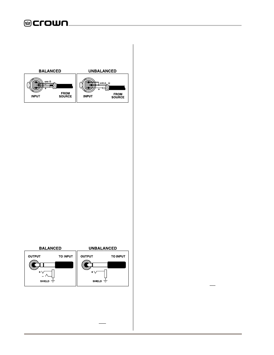
3.7 A Closer Look at Audio Signal Wiring
Balanced 3-pin female XLR connectors are provided
for audio input connection. The audio cables should
be wired in one of the following manners:
plifier (if provided). The phone jacks are wired in paral-
lel with the output of the
P.I.P. connector inside the am-
plifier. Any audio signal fed into the phone jacks could
feed back into the output of the
IQ–P.I.P.–DSP and gen-
erate a distorted input signal. The phone jacks can be
used to “daisy chain” the post-processed signal from
the
IQ–P.I.P.–DSP to the inputs of other amplifiers.
DO NOT USE THE CHANNEL 2 INPUT if the amplifier
is used in either Bridge-Mono or Parallel-Mono mode.
For additional information on audio input connection
please refer to the amplifier’s
Reference or Owner‘s
Manual. It contains helpful information on preventing
unwanted subsonic frequencies, radio frequency inter-
ference, ground loops, and feedback oscillation.
3.8 When External Power is Needed
The
IQ–P.I.P.–DSP draws 320 mA at +24 VDC and 160
mA at –24 VDC. Many Crown amplifiers can provide
this power via the
P.I.P. edge connector inside. For
these
IQ–P.I.P.-DSP/amplifier combinations, no exter-
nal power supply is needed. Amplifiers which can sup-
ply adequate power include all
Com-Techs, all
Macro-Tech 5000VZ, all Studio Reference amplifiers
and all
PIP2-compatible amplifiers. For IQ–P.I.P.-DSP
installations into 50-Hz versions of
Macro-Tech amplifi-
ers (excluding the
Macro-Tech 5000VZ), Crown rec-
ommends use of the S4 version of these amplifiers.
Please contact Crown Technical Support for more in-
formation about power supply options for the 50-Hz
Macro-Tech versions.
Other Crown
P.I.P.-compatible amplifiers may not be
able to supply the full 320 mA of +24 VDC power for
the
IQ–P.I.P.–DSP, depending on how well regulated
the AC mains are that feed them and how hard the
amplifiers are driven. This includes the
Macro-Tech
600, 1200, 2400, 24x6, 3600VZ and 36x12. We sug-
gest that a 400 mA +24 VDC supply be added for
these amplifiers as a safety measure to be certain that
adequate power is available.
Note: Actually, external
power of only 200 mA is needed for these amplifiers,
but a 400 mA supply is recommended to be certain
that the external supply, itself, has a safety margin. A
mini jack is provided on the
P.I.P. panel of the IQ–P.I.P.–
DSP for external power connection.
IMPORTANT:
The
IQ–P.I.P.–DSP cannot be operated
from an external power supply if the enable switch of
the amplifier is turned off. The amplifier is required to
provide –24 VDC.
CAUTION:
If external power is needed, use an indi-
vidual, isolated power supply for each
IQ–P.I.P.–DSP.
Do not attempt to share a common power supply with
multiple
IQ–P.I.P.–DSP modules or the IQ–P.I.P.–DSP
modules may be damaged.
Fig. 3.11 Audio Input Wiring
We strongly recommend that balanced wiring be used
if possible. Some important guidelines follow:
• Always use shielded wire. The higher the density
of the shield (the outer conductor), the better.
Spiral wrapped shield is not recommended.
• When using unbalanced lines, keep the cables
as short as possible. Avoid lengths greater than
10 feet (3 meters).
• Do not run audio input cables together with
high-level wiring such as loudspeaker wires or
AC cords. (This lessens the chance of hum or
noise being induced into the input cables.)
• Do not connect audio and data grounds to-
gether. For example, do not connect the audio
ground to the Crown Bus ground.
• Turn the entire sound system off before chang-
ing any connections. Turn the level controls
down before powering the system back up.
Crown is not liable for damage incurred when
any transducer or component is overdriven.
Balanced phone jacks are provided for “daisy chain”
audio output connection. The audio cables should be
wired in one of the following manners:
Fig. 3.12 Audio Output Wiring
In order to comply with FCC and EC EMC regulations,
it is necessary to add an EMI (electro-magnetic inter-
ference) core to the daisy chain cable(s). A core, large
enough to snap over both cables, is provided.
IMPORTANT:
Do not feed a signal into the phone
jacks on the
IQ–P.I.P.–DSP or the back panel of the am-