Iq system, Communications, 4 microprocessors and reset switch – Crown Audio IQ P.I.P.-DSP User Manual
Page 22: 2 control/monitor functions, 3 dspi control, Iq–p.i.p.–dsp, P.i.p, 1 audio signals, 2 status signals, Odep
Page 22
IQ–P.I.P.–DSP Programmable Input Processor with DSP for IQ Systems
Reference Manual
5.2.3 DSPI Control
The DSPI LED flashes whenever a valid IQ command has
been received and can be forced to stay on to facilitate
diagnosis of Crown Bus wiring problems.
5.3
IQ System
Communications
The
IQ–P.I.P.–DSP
communicates with the host computer
via the Crown Bus. Connections to the Crown Bus are
made via the 4 and 5-pin locking DIN connectors on the
rear panel. IQ commands entering the
P.I.P.
are fed into
an input receiver circuit that converts the 20 mA current
loop signal into a standard logic signal that the 6811 mi-
croprocessor can understand. This signal is also passed
directly to the Crown Bus for output where it is passed on
to the remainder of the loop. Data sent in response to IQ
commands is also sent through the Crown Bus output
where it passes through the remainder of the loop and
back to the host computer. A “drop out” relay is also
present which makes a physical contact between the
Crown Bus input and output connectors in the event of a
power failure. This means that as long as the Crown Bus
cables are connected to the
P.I.P.
, the Crown Bus will re-
main unbroken—even if power to the
P.I.P.
is lost.
5.4 Microprocessors and Reset Switch
The “brains” of the
IQ–P.I.P.–DSP
are contained in its two
microprocessors. A Motorola 6811 interprets commands
received from the Crown Bus and responds accordingly.
A Motorola 56002 manages all DSP functions. The
memory of both processors is backed up with EEPROM.
The
IQ–P.I.P.–DSP
is designed to provide an “automatic
reset” in the event of a power failure, but the rear reset
switch has also been added. Pressing this switch restores
all
P.I.P.
settings to the “user defaults” if it is pressed for
less than 2 seconds or to the factory defaults if it is
pressed for more than 2 seconds. The only exception is
the initialization data which can only be changed with
IQ
System
software on the host computer.
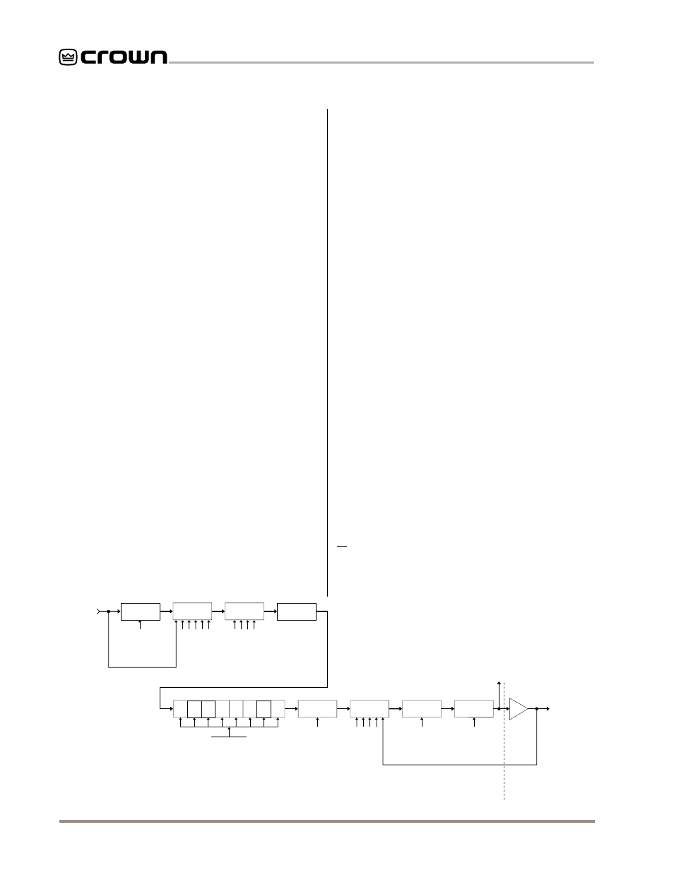
parameters are used here such as threshold, attack time,
etc. Next, the output limiter is processed through control-
lable polarity inverters. The last processing section is an
output muter after which the signal is sent to the main am-
plifier for voltage and current amplification.
All parameters are continuously controllable via the
IQ
System
or can be set and will continue to operate.
5.2 Control/Monitor Functions
5.2.1 Audio Signals
In addition to controlling the audio input level and polarity,
the
IQ–P.I.P.–DSP
can turn on/off the high-voltage power
supplies. These functions are controlled using ports on
the 6811 microprocessor and some external support cir-
cuitry. The audio level is controlled by the 6811 micropro-
cessor through a digitally controlled analog attenuator.
The audio signals that are monitored are the input to the
P.I.P.
and the output of the amplifier. These signals enter
the
P.I.P.
and are fed into a precision peak detector which
insures that instantaneous signal peaks are not “missed”
by the
P.I.P.
The detector outputs are then fed through a
multiplexer into a logarithmic conversion circuit for dy-
namic range scaling. The output of this circuit is then fed
into the A/D converter on the 6811 microprocessor, where
the signal is converted and sent to the host computer via
the Crown Bus.
5.2.2 Status Signals
The status signals that are monitored are
ODEP
level,
IOC
status and VCC status. These signals enter the
P.I.P.
, pass
through a buffer stage, and are fed into the A/D converter
on the 6811 microprocessor. The signals are then con-
verted and sent to the host computer via the Crown Bus.
SIGNAL
DELAY
OUTPUT
LIMITER
POLARITY
INVERTER
OUTPUT
MUTER
MAIN
AMPLIFIER
FLTR
1
FLTR
2
FLTR
3
FLTR
4
FLTR
5
FLTR
6
FLTR
7
FLTR
8
DELAY
ON/OFF
THRESHOLD
ATTACK TIME
RELEASE TIME
INVERT / NORMAL
MUTE / UNMUTE
ON/OFF
FILTER TYPE
FILTER Q
FILTER FREQUENCY
FILTER GAIN
IQ-P.IP.-DP
AMPLIFIER
DAISY CHAIN
OUTPUT
INPUT
ATTENUATOR
INPUT
COMPRESSOR
ODEP CONSER-
VATION LIMITER
INPUT PROTEC-
TION LIMITER
ATTENUATION
ON/OFF
THRESHOLD
ATTACK TIME
RELEASE TIME
RATIO
ON/OFF
TRIGGER LEVEL
CONSERVATION AMOUNT
RELEASE TIME
Fig. 5.2 IQ–P.I.P.–DSP Audio Signal Flow Block Diagram