Warning – Carrier T--298 User Manual
Page 33
T--298
3-9
3.5.8
Capacitor Troubleshooting
WARNING
Disconnect power to the AirV unit before
checking the capacitor.
To test capacitor to determine if good, open or shorted,
an ohm meter can be used. To determine a capacitor’s
capacitance, a capacitor meter is required.
Capacitors showing signs of leaks or bulging should be
replaced immediately.
3.5.9
Capacitor Testing and Replacement
Capacitors must be discharged properly before testing.
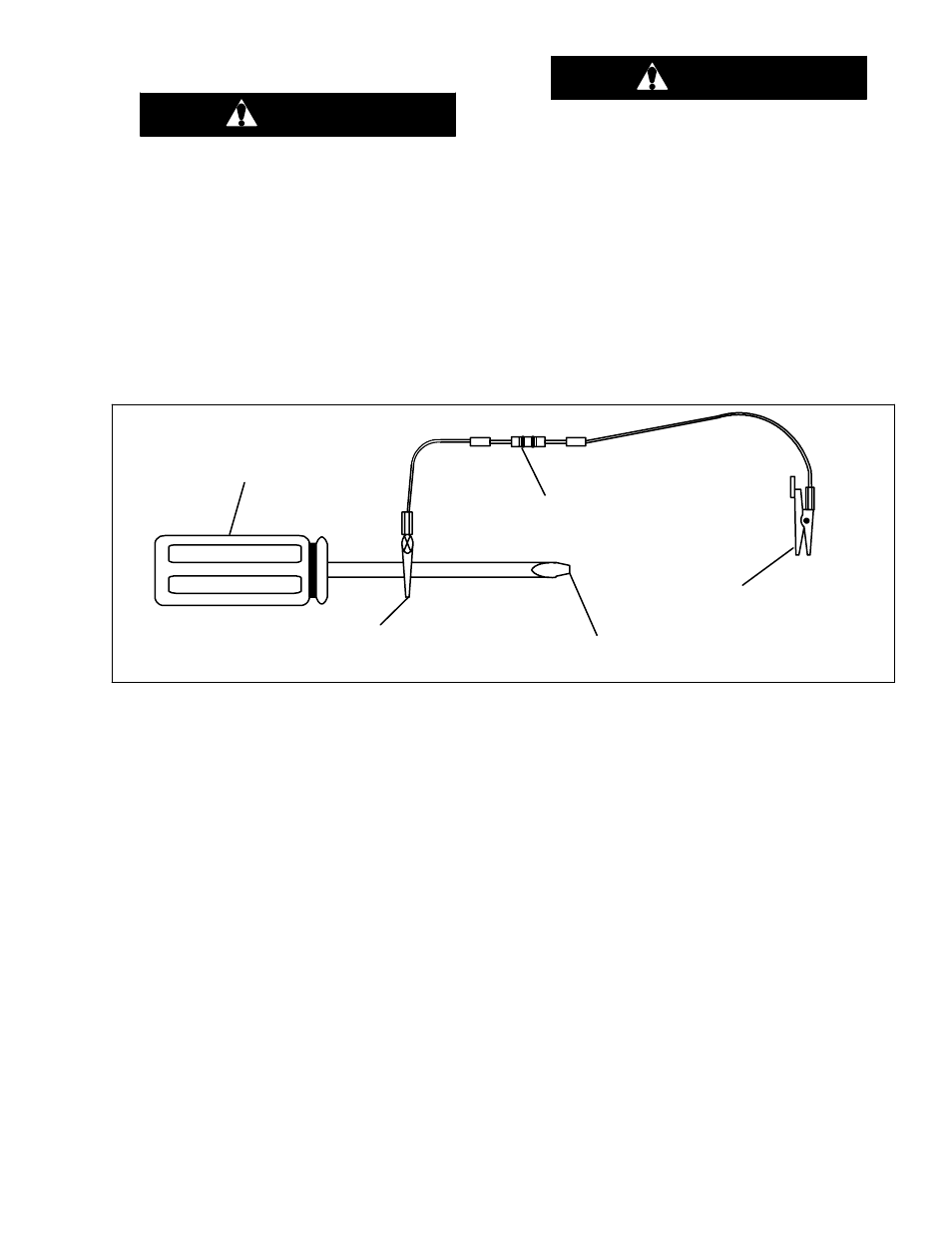
a. Place a 20,000 ohm, 2 watt resistor across the termi-
nals of the capacitor for approximately 30 seconds
(See Figure 3-25 for a suggested tool).
WARNING
Do not touch the metal of the screwdriver
when discharging the capacitor. You could
receive a shock.
b. After the capacitor has been discharged and all wires
removed from the capacitor terminals, use an ohm--
meter to test its resistance.
c. Set the scale to R x 1K or 10K ohm and place the
ohmmeter leads across the capacitor terminals.
d. If the ohmmeter first reads 0, then rises toward infinity
or some higher resistance, the capacitor is good.
e. If the ohmmeter goes to 0 or a low resistance and
stays there, the capacitor is shorted and needs to be
replaced.
f. If the ohmmeter reads infinity (OL) the capacitor is
open and needs to be replaced.
CLIP TO
SCREWDRIVER
TOUCH TO CAPACITOR TERMINALS
TO DISCHARGE CAPACITOR
20,000 -- OHM
2 -- WATT RESISTOR
INSULATED SCREWDRIVER
ATTACH TO CLEAN UNPAINTED
METAL PART OF UNIT FRAME
Figure 3-25 Set--Up For Discharging a Capacitor
3.5.10 Positive Temperature Coefficient Thermister
(PTC) (Start Thermistor) Troubleshooting
a. Disconnect power from the AirV unit.
b. Disconnect the wires to the PTC.
c. Using an ohm meter, check for continuity across the
PTC.
If the PTC does not have continuity, it must be replaced.
If continuity exists, reconnect the wires to the PTC.
d. Reconnect power to the AirV unit.
e. Turn on the AirV unit to start.
f. Use a clamp--on amp probe to monitor the amp draw
of the compressor during its start--up.
When the compressor starts, an amp draw will be
indicated for almost a second.
If no amp draw is indicated or if the amp draw occurs for
much longer than a second, the PTC is defective and
must be replaced.
3.5.11 Line Voltage -- 10%
Line voltage should be checked during peak electrical
load periods.
With the AirV unit on and the compressor operating, use
a voltmeter to check the voltage being supplied to the
AirV unit. The voltage must be within 10% of the units
required voltage. A voltage drop greater than 10% will
cause a premature compressor failure and needs to be
corrected immediately.