Caution – Carrier T--298 User Manual
Page 29
T--298
3-5
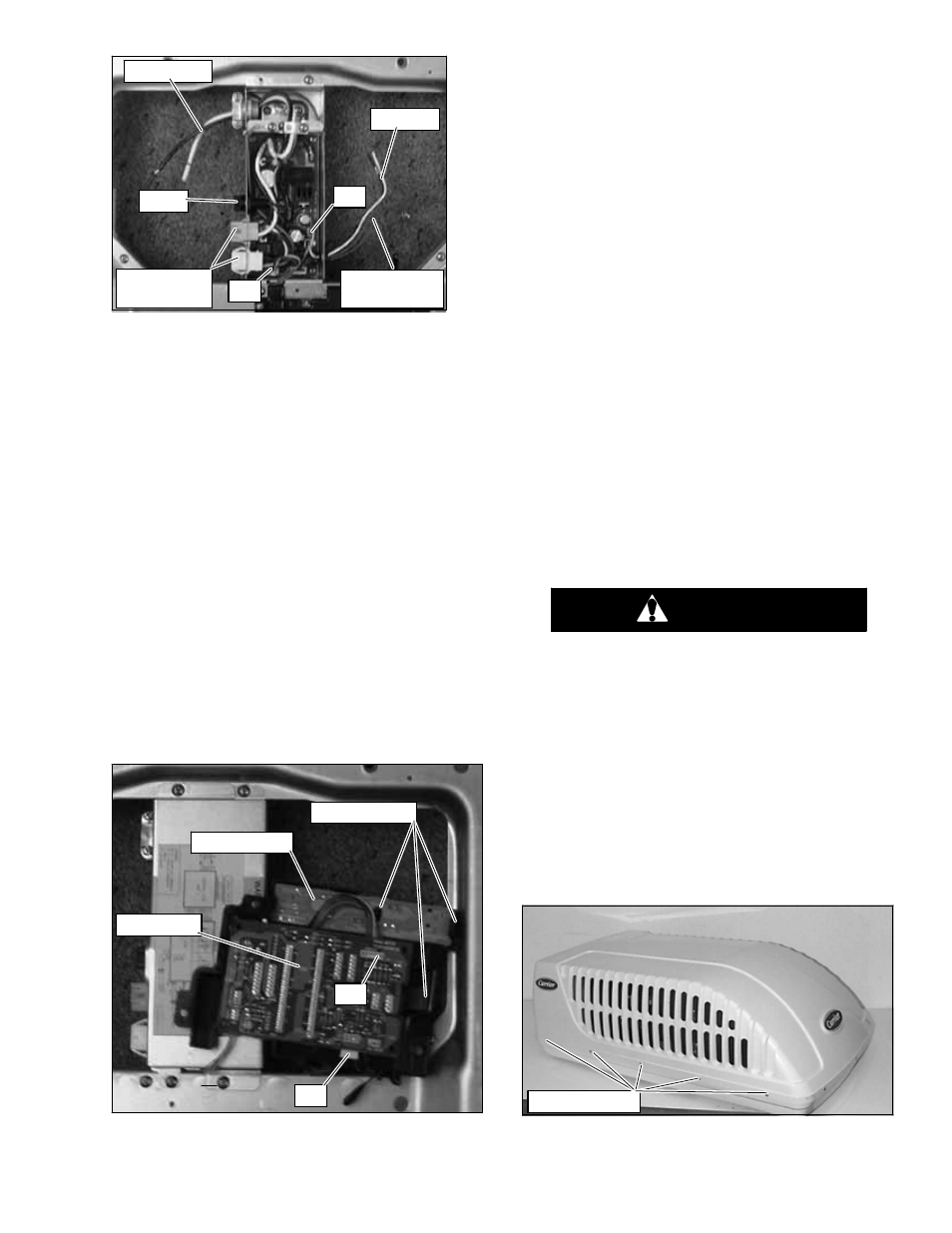
115V AC
12V DC
Fuse
Upper Unit
Connectors
Furnace
Wires (blue)
#1
#2
Figure 3-12 Control Box Assembly -- Ducted
3.4.4 Main PCB Board Removal
To remove the Main PCB board (Figure 3-13) do the
following:
a. Remove ceiling grill. Refer to paragraph 3.4.2.
b. Remove three screws securing the PCB cover to the
ducted ceiling unit.
c. Carefully turn over the PCB cover exposing the PCB
main and the PCB display assemblies.
d. Gently push holding clip away from PCB main assem-
bly.
e. Lift PCB main assembly from PCB cover assembly.
f. Unplug display wiring plug #4. Figure 3-13
g. Unplug
thermistor/thermostat
wiring
plug
#3.
Figure 3-13
h. Unplug power wiring plug #1. Figure 3-12
i. Unplug signal wiring plug #2. Figure 3-12
j. Reverse above procedures for reassembly.
Holding Clips
PCB Display
PCB Main
#3
#4
Figure 3-13 Main/Display PCB’s
3.4.5 PCB Display Removal
To remove the PCB display assembly (Figure 3-13) do
the following.
a. Remove ceiling grill. Refer to paragraph 3.4.2.
b. Push large clip away from PCB display assembly.
c. Push center clip towards large clip.
d. Pull PCB display assembly from PCB cover.
e. Unplug display wiring from PCB main assembly.
f. Reverse above procedures of reassembly.
3.4.6 Fuse Removal
To remove the fuse (Figure 3-11) do the following:
a. Remove ceiling grill. Refer to paragraph 3.4.2.
b. Turn fuse holder in direction of arrow (counter-- clock--
wise).
c. Pull fuse from fuse holder.
d. Test and/or replace.
e. Reverse above procedures for reassembly.
3.5
SERVICE -- UPPER UNIT -- STANDARD,
HC & HP
3.5.1 Exterior Cover Removal
CAUTION
Coil fins are sharp. Use care when removing
the cover form the base pan to avoid per-
sonal injury.
To remove the exterior cover, do the following:
a. Before working on unit place the master switch in the
OFF position and disconnect all electrical power.
b. Remove 15 screws securing the unit cover to the
base pan assembly. See Figure 3-14.
c. Carefully lift the exterior cover off of the unit base pan
assembly.
d. Reverse above procedure for reassembly.
Cover Screws
Figure 3-14 Cover Assembly -- Standard