Carrier T--298 User Manual
Page 18
T--298
1-9
1.4
AirV SYSTEM COMPONENT SPECIFI-
CATIONS
1.4.1 Refrigerant Charge
Standard -- High Capacity -- Heat Pump
R--22 -- 15.9 Ounces
Low Profile (All)
R--22 -- 16.9 Ounces
1.4.2 Compressor -- 115 Volts, 60 Cycles, 1 Phase
a. Locked Rotor Amps -- Standard -- High
Capacity -- Heat Pump
64.5 AMPS6
b. Locked Rotor Amps -- Low Profile
High Capacity
59.0 AMPS
c. Fully Loaded Amps -- Standard
Cooling -- Approximate 12.8 AMPS
Heating -- N/A
d. Fully Loaded Amps -- High Capacity
Cooling -- Approx. 14.5 AMPS
Heating -- Approx. 11 AMPS
e. Fully Loaded Amps -- Low Profile
Cooling -- Approx. 14.1 AMPS
Heating -- Approx. 13.8 AMPS
f. Fully Loaded Amps -- Heat Pump
Cooling -- Approx. 12.8 AMPS
Heating -- Approx. 11 AMPS
1.4.3 Compressor -- 220 Volts, 50 Cycles, 1 Phase
a. Locked Rotor Amps
23.6 AMPS
1.4.4 Thermostat Range (All Free Blow Units)
61
°
F (16
°
C) to 89
°
F (32
°
C)
1.5
START--UP
Refer to operating instructions in Owners Guide (see
Table 1-2) packaged with the vehicle system.
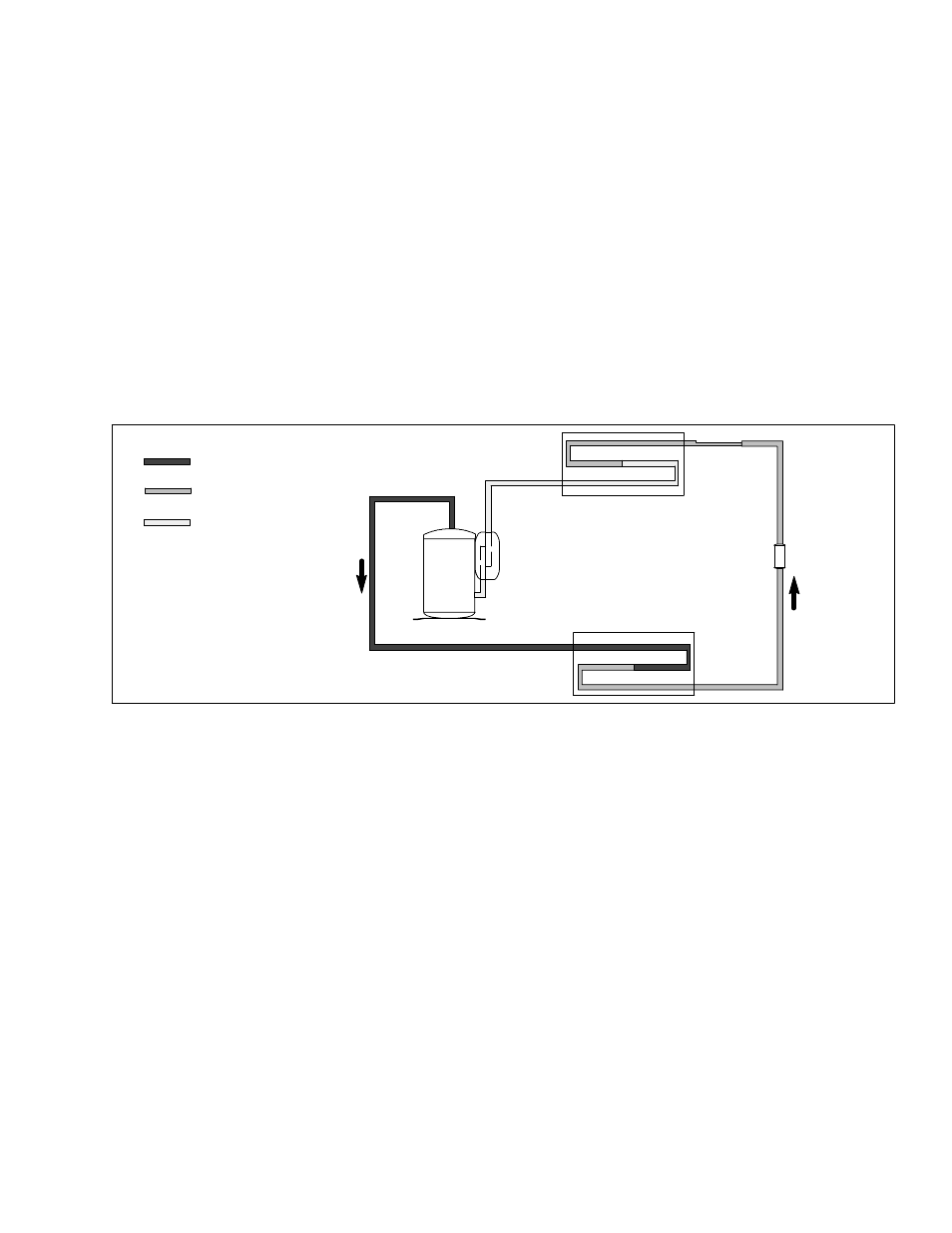
COMPRESSOR
ACCUMULATOR
CONDENSER
EVAPORATOR
CAPILLARY
TUBE
STRAINER
DISCHARGE
SUCTION
LIQUID
Figure 1-8 Refrigerant Flow Schematic (Standard System)
1.6
REFRIGERANT CYCLE--STANDARD SYSTEM
The cooling cycle is energized when the thermostat,
located on the ceiling unit, calls for cooling. The main
components of the system are the compressor,
air-cooled condenser coil, strainer, capillary tube,
evaporator coil and accumulator.
The
compressor
raises
the
pressure
and
the
temperature of the refrigerant and forces it through the
discharge line into the condenser coil. (See Figure 1-8.)
The condenser fan circulates surrounding air (which is
at a temperature lower than the refrigerant) over the
outside of the coil tubes. Heat transfer is established
from the refrigerant (inside the tubes) to the air (flowing
over the tubes). The tubes have fins designed to
improve the transfer of heat from the refrigerant gas to
the air. This removal of heat causes the refrigerant to
liquefy, thus liquid refrigerant leaves the coil and flows
through a strainer to the capillary tube. The strainer
removes any impurities within the refrigerant system.
The capillary tube meters the flow of liquid refrigerant to
the evaporator coil. As the refrigerant flows through the
capillary tube, there is a reduction in pressure and
temperature.
The evaporator blower (fan) pulls vehicle air through the
filters, which remove particulate matter, and then pass
the cleaned air through the evaporator coil.
The low pressure, low temperature liquid that flows into
the evaporator coil tubes is colder than the air that is
circulated over the tubes. Heat transfer is established
from the vehicle air (flowing over the tubes) to the
refrigerant (flowing inside the tubes). The evaporator
coil tubes have aluminum fins to increase heat transfer
from the air to the refrigerant; therefore the cooler air is
circulated to the interior of the vehicle.
The transfer of heat from the air to the low temperature
liquid refrigerant in the indoor coil causes the liquid to
vaporize. This low temperature, low pressure vapor
passes into the accumulator. The accumulator is
designed with the inlet tube delivering refrigerant to the
bottom of the tank and the outlet tube taking refrigerant
form the top of the tank. This arrangement ensures that
only vapor refrigerant is returned to the compressor,
where the cycle repeats.
When ventilation only is selected, the indoor fan
functions to circulate air throughout the vehicle. The
refrigerant cycle will remain off.