6signal sequence – Baumer BA Scatec2 User Manual
Page 5
Manual SCATEC-2
9
Baumer Electric AG
Version 2011-05
www.baumer.com
Frauenfeld, Switzerland
Overlap: a
Distance between two successive edges, measured along the
conveying plane. (Also referred to as the object spacing.)
Edge thickness: k
Thickness of the copy at the point where the edge is to be detected.
Front edge
The edge of an object facing the laser beam. Front edges are detected
by the sensor.
Tail edge
The edge of an object facing away from the laser beam. Tail edges are
not detected by the sensor unless they are pointing upwards.
Running direction
The preferred running direction (front edges leading) is indicated. The
opposite direction is also permitted by the SCATEC-2.
Dead time t
The sensor responds to an edge with an output pulse with length p.
The dead time begins when the
pulse is issued. The sensor can
only issue the next pulse after
both the dead time t and the
output pulse p have expired. This
means: an edge detected by the
beam while still either the dead
time t or the the output pulse p is
on does not initiate an output
pulse.
False pulse
Output pulse generated by an edge which should not be counted.
Output pulse
Dead time
p
t
Manual SCATEC-2
10
Baumer Electric AG
Version 2011-05
www.baumer.com
Frauenfeld, Switzerland
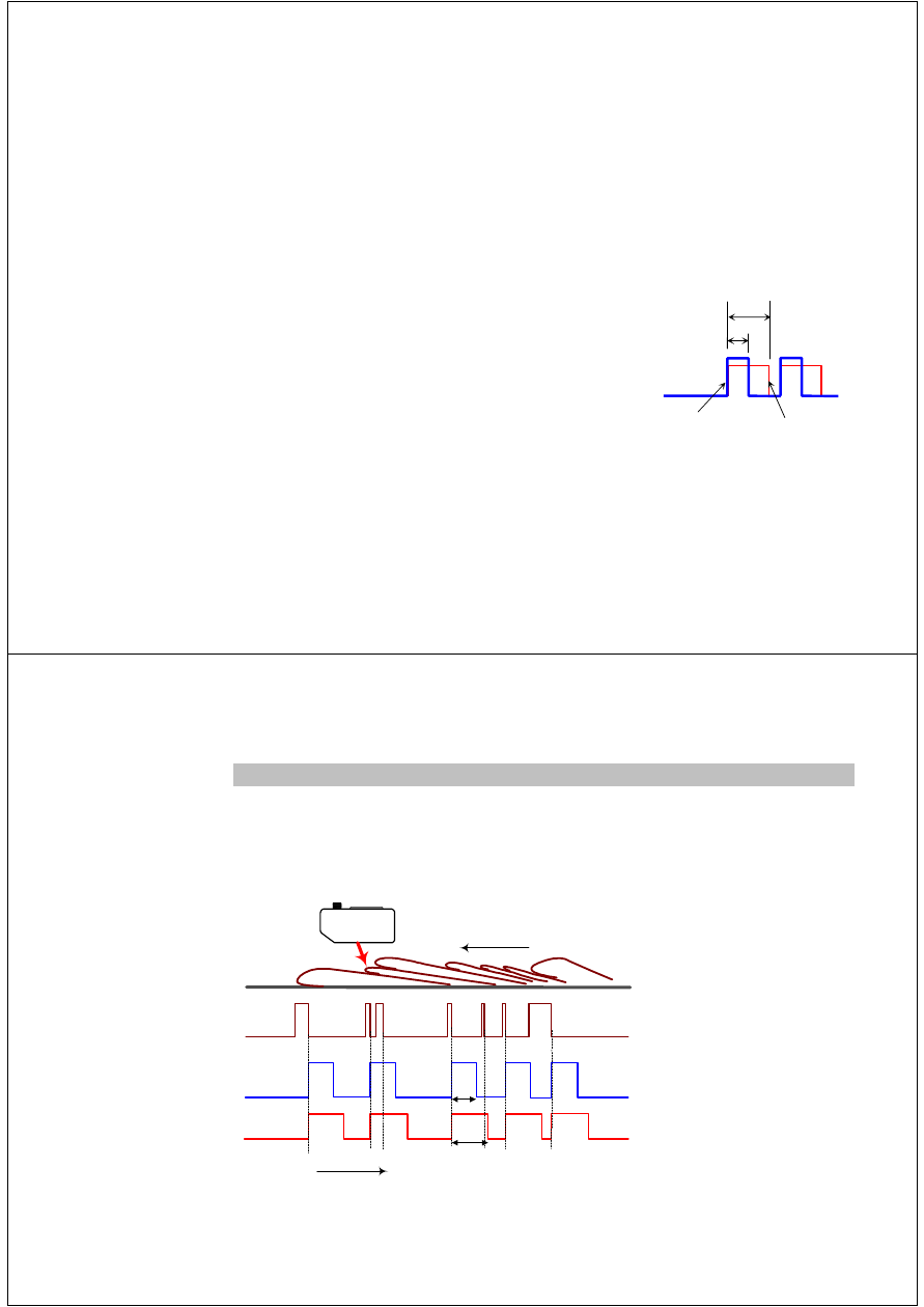
6
Signal sequence
The yellow edge indicator LED lights as long as an edge is located in the beam. The output pulse is
issued at the end of the edge. The dead time begins when the output pulse is issued. During the dead
time and when issuing the pulse, the SCATEC-2 is inactive, i.e. an edge ending during the dead time or
the pulse issue of the previous edge will not initiate an output pulse. Therefore, the next output pulse
can only be issued after the dead time has expired and the output pulse has been issued.
yellow edge-LED
output pulse (pulse length: p)
dead time (period: t )
Running direction
on
off
high
low
on
off
time
t
p