Baumer BA Scatec2 User Manual
Page 12
Manual SCATEC-2
23
Baumer Electric AG
Version 2011-05
www.baumer.com
Frauenfeld, Switzerland
10.2
Electrical data
Operating voltage V
S
Limits:
+10 VDC to +30VDC (UL-Class 2)
reverse-protected
yes
Ripple V
S
10% within the limits of V
S
Power consumption
< 2 W
Current consumption
Average:
< 170 mA
Peak (after switching on)
< 180 mA
Output connector
FLDK.../S14
M12 connector, 5-pole
FLDK.../S42
DIN 45322, 6-pole
FLDK110x10/xxxxxx
see section 14
Output circuit
FLDK 110G...
Push-pull
normal state
low
FLDK 110C...
Opto-isolated
switchable voltage
maximum 40 V
load resistance
maximum 50 kOhm
current load:
max. 100 mA
short-circuit protected
yes
Output pulse length
FLDK...1003/…and ...1005/…
5, 10, 15, 20 ms selected by DIP switch
FLDK...1006/…
5, 10 ms selected by DIP switch
Manual SCATEC-2
24
Baumer Electric AG
Version 2011-05
www.baumer.com
Frauenfeld, Switzerland
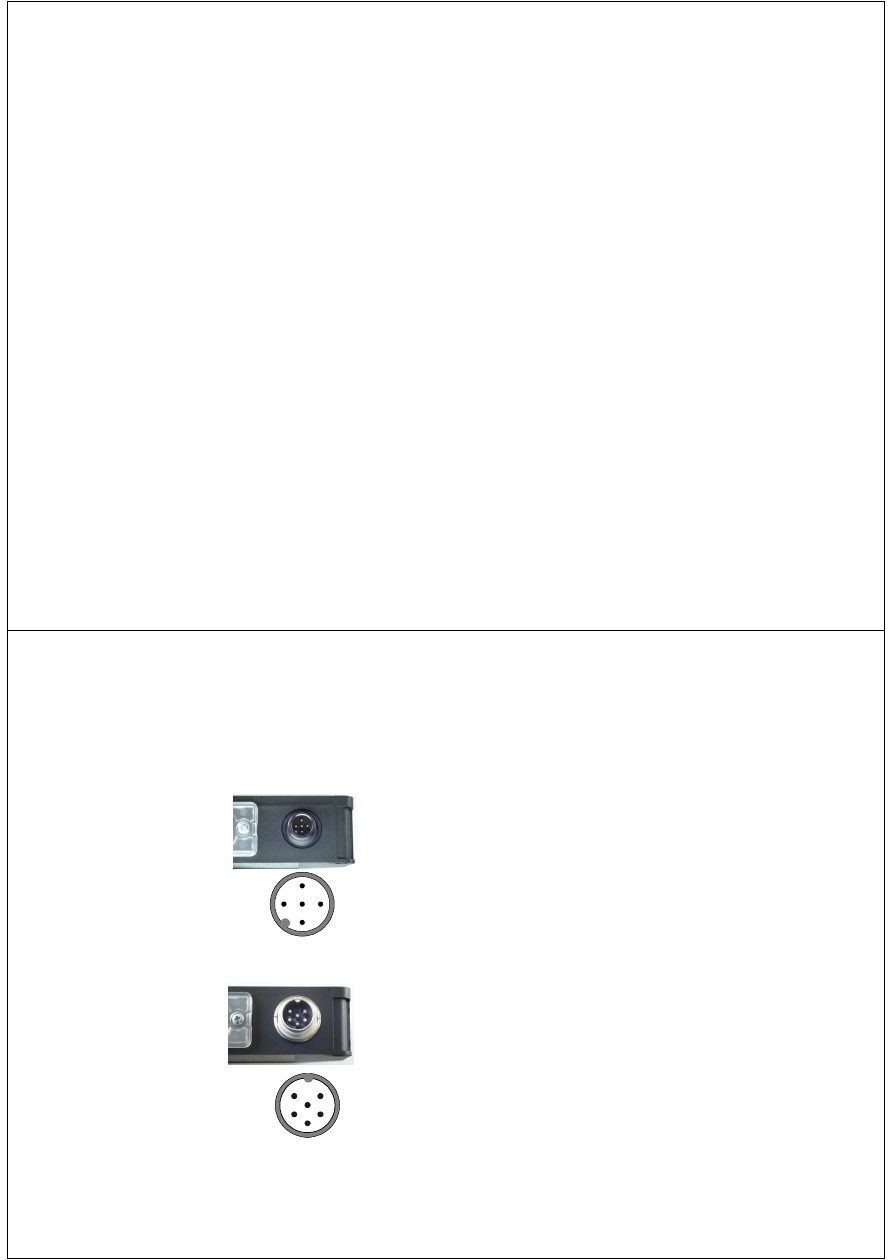
10.3
Pin assignment
FLDK.../S14
M12-connector, 5-pole
FLDK.../S42
DIN 45322, 6-pole
Pin Assignment
1
Operating voltage +Vs
2
Seriell TxD (sensor)
3
GND (0V)
4
Signal output +Vout
5
Seriell RxD (sensor)
Pin Assignment
1
Signal output +Vout
2
not connected
(FLDK 110G...)
Signal output -Vout
(FLDK 110C...)
3
Operating voltage +Vs
4
Seriell RxD (sensor)
5
Seriell TxD (sensor)
6
GND (0V)
3
1
2
5
4
3
4
2
1
5
6