Ex na ii t4/t5, atex ii 3g electrical connection, Ex na - installation – Baumer Flex Bar HRT User Manual
Page 6
Page 6
Design and specifi cations subject to change without notice
Installation Manual
www.baumerprocess.com
Ex-data
Supply range 6.5...35
VDC
Temperature class
T1...T4:
-10 < T
amb
< 85°C
T5:
-10 < T
amb
< 60°C
Ex nA II T4/T5, ATEX II 3G
Electrical Connection
Electrical Connection
Cable diameter
Torque
mm
Nm
Gland M20, plast
8...13
8
Plug DIN-B
6...8
4
Plug DIN-A
8...10
3
Gland M16
3...9
8
Plug M12
-
4
A FlexBar HRT with the type number 81 6x3 xxx xxxx is Ex nA II
T4/T5 and ATEX II 3G approved for application in hazardous areas in
accordance with the current EU-directives.
The FlexBar HRT must be installed in accordance with prevailing
guidelines for zone 2 without a barrier.
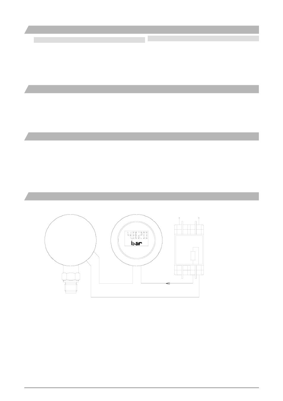
Ex nA - Installation
Ex nA - Installation
FlexBar HRT
FlexView display
Power
(Optional)
Supply
230 VAC
24 VDC
4...20 mA
+
-
Opto-relay
Voltage, standard Max.
230
VAC
Voltage, GL-approved Max.
60
VAC
DC-voltage Max.
50
VDC
Current, continuously
Max. 50 mA
Current, pulse
Max. 500 mA
Relay function Set/reset
If the FlexBar HRT has the relay option (type numbers 81 62 3xxx
xxxx and 81 64 3xxx xxxx) the connections to the relay must be carried
out according to the rules for an intrinsically safe installation.
The FlexBar HRT must be connected in the 4...20 mA loop circuit only.
Warning: If the FlexBar HRT is to be installed in ambient
temperature exceeding 70°C a proper cable should be installed.
-
+
-
+