Ex ia iic t5/t6, atex ii 1g ex ia - installation – Baumer Flex Bar HRT User Manual
Page 5
Page 5
Design and specifi cations subject to change without notice
Installation Manual
www.baumerprocess.com
A FlexBar HRT with the type number 81 6x2 xxx xxxx is Ex ia IIC
T5/T6 and ATEX II 1G approved for application in hazardous areas in
accordance with the current EU-directives.
A certifi ed Ex ia or isolation barrier with the maximum values
U
max
= 30 VDC ; I
max
= 0.1 A ; P
max
= 0.75 W must be used.
Ex-data
Supply range 6.5...30
VDC
Internal inductivity
L
i
< 10 µH
Internal capacity
C
i
< 1 nF
Barrier data
U < 30 VDC ; I < 0.1 A ; P
< 0.75 W
Temperature class
T1...T5:
-10 < T
amb
< 70°C
T6:
-10 < T
amb
< 50°C
Ex ia IIC T5/T6, ATEX II 1G
Ex ia - Installation
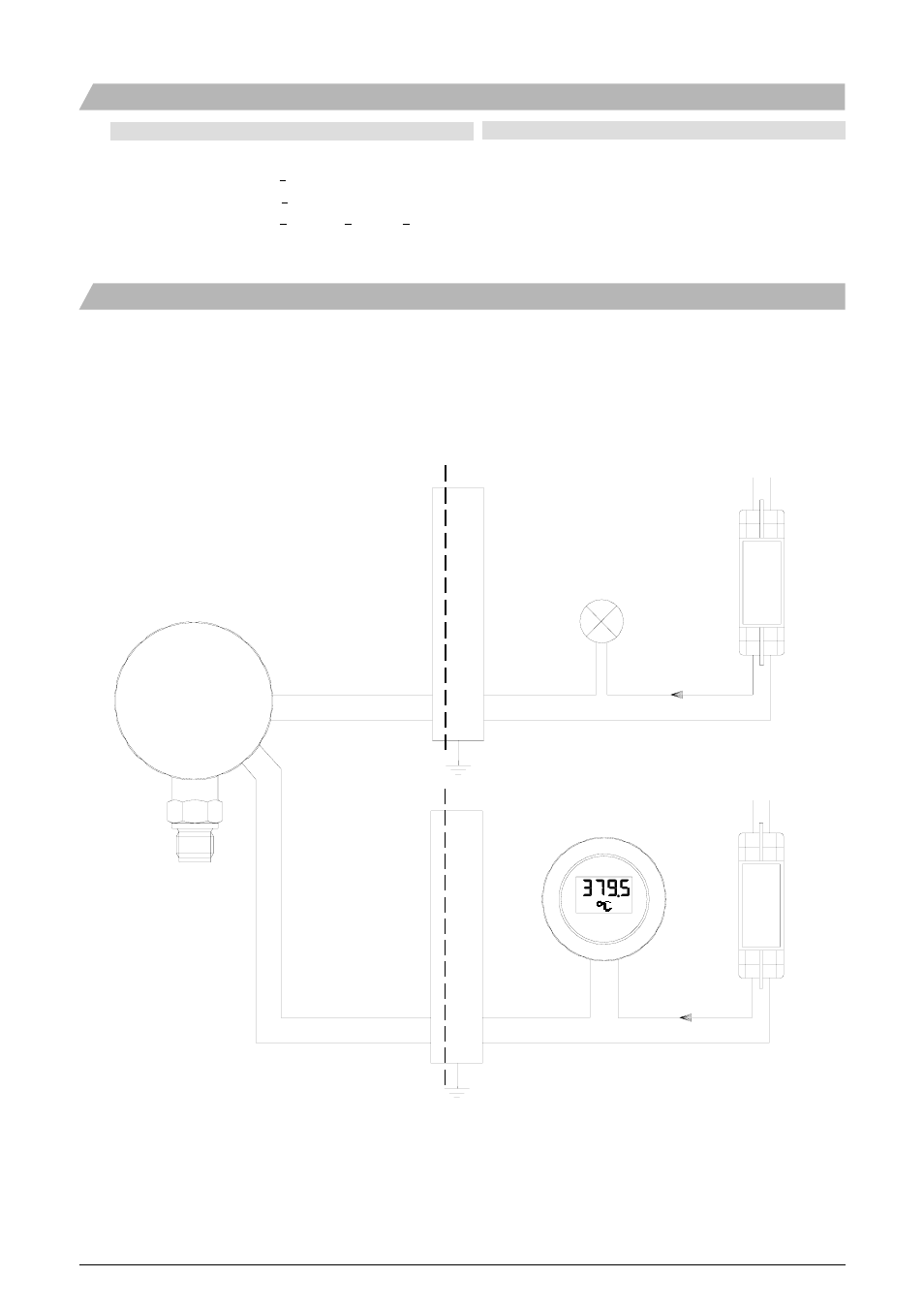
If the FlexBar HRT has the relay option (type numbers 81 62 xxxx
xxxx and 81 64 xxxx xxxx) the connections to the relay must be carried
out according to the rules for an intrinsically safe installation.
The FlexBar HRT must be connected in the 4...20 mA loop circuit only.
Zone 0/1
Safe area
Barrier
FlexView display
Power
(Optional)
Supply
FlexBar HRT
with relay and cover
Lamp
230 VAC
24 VDC
4...20 mA
3 4
1 2
+
-
230 VAC
24 VDC
4...20 mA
3 4
1 2
+
-
Zone 0/1
Safe area
-
+
Relay
4..20 mA
3
4
1
2
Opto-relay
Voltage, standard Max.
230
VAC
Voltage, GL-approved Max.
60
VAC
DC-voltage Max.
50
VDC
Current, continuously
Max. 50 mA
Current, pulse
Max. 500 mA
Relay function Set/reset