Step 6 — provide for condensate disposal – Carrier 50JZ-A User Manual
Page 8
8
7. Flash, weatherproof, and vibration--isolate all openings in
building structure in accordance with local codes and good
building practices.
Step 6 — Provide for Condensate Disposal
NOTE: Ensure that condensate--water disposal methods comply
with local codes, restrictions, and practices.
The 50JZ--A units dispose of condensate through a 3/4 in. NPT
female fitting that exits on the compressor end of the unit.
Condensate water can be drained directly onto the roof in rooftop
installations (where permitted) or onto a gravel apron in ground
level installations. Install a field--supplied condensate trap at end of
condensate connection to ensure proper drainage. Make sure that
the outlet of the trap is at least 1 in. (25 mm) lower than the
drain--pan condensate connection to prevent the pan from
overflowing. Prime the trap with water. When using a gravel apron,
make sure it slopes away from the unit.
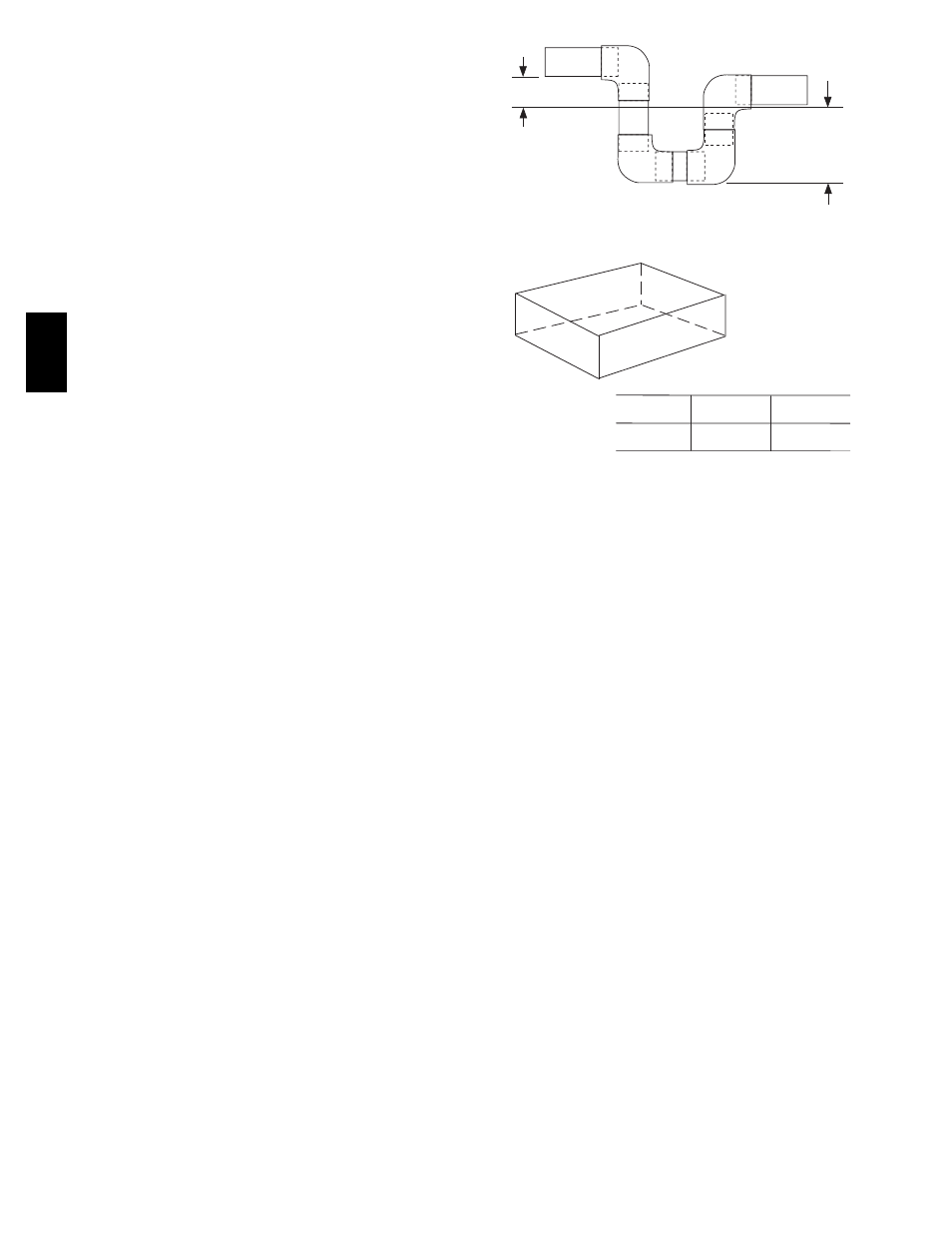
If the installation requires draining the condensate water away from
the unit, install a field--supplied 2 --in. (51mm) trap at the
condensate connection to ensure proper drainage. Condensate trap
is available as an accessory or is field--supplied. Make sure that the
outlet of the trap is at least 1 in. (25 mm) lower than the unit
drain--pan condensate connection to prevent the pan from
overflowing. Connect a drain tube using a minimum of
field--supplied 3/4--in. PVC or field--supplied 3/4--in. copper pipe
at outlet end of the 2--in. (51 mm) trap. (See Fig. 8.) Do not
undersize the tube. Pitch the drain tube downward at a slope of at
least 1 in. (25 mm) every 10 ft (3 m) of horizontal run. Be sure to
check the drain trough for leaks. Prime the trap at the beginning of
the cooling season start--up.
TRAP
OUTLET
1-in. (25 mm) min.
2-in. (51 mm) min.
A09052
Fig. 8 -- Condensate Trap
A
B
C
MAXIMUM ALLOWABLE
DIFFERENCE in. (mm)
A-C
1/4
1/4
1/4
(6.35)
(6.35)
(6.35)
A-B
B-C
A07925
Fig. 9 -- Unit Leveling Tolerances
50J
Z
--
A