Carrier 50JZ-A User Manual
Page 11
11
Accessory Electric Heaters Installation
Electric heaters may be installed with the 50JZ--A units per
instructions supplied with electric heater package. See unit rating
plate for factory--approved electric heater kits.
Sequence of Operation
a. CONTINUOUS FAN
(1.) Thermostat closes circuit R to G energizing the
blower motor for continuous fan.
b. COOLING MODE
(1.) If indoor temperature is above temperature set
point, thermostat closes circuits R to G, R to Y1
and R to O (Y2). The compressor, indoor and
outdoor fans, and reversing valve are energized.
c. ELECTRIC HEATING MODE
(1.) Thermostat closes circuit R to W/W1, or W2 and R
to G. There are no on or off delays.
d. HEAT PUMP HEATING MODE
(1.) Thermostat closes circuits R to G and R to Y1. The
compressor, indoor and outdoor fans are energized.
e. HEAT PUMP HEATING WITH AUXILIARY
ELECTRIC HEAT
(1.) Thermostat closes circuits R to G, R to Y1 and R
to W/W1 or W2. The compressor, indoor and
outdoor fans are energized, as well as the electric
heat relays.
f. DEFROST MODE
The defrost mode is automatically energized by the
defrost board during heating mode. The defrost board
energizes “O” (reversing valve) and “W2” (electric
heat). It also de--energizes the outdoor fan. When defrost
is complete, unit will return to heating mode. If room
thermostat is satisfied during defrost, unit will shut
down and restart in defrost on next call for heat.
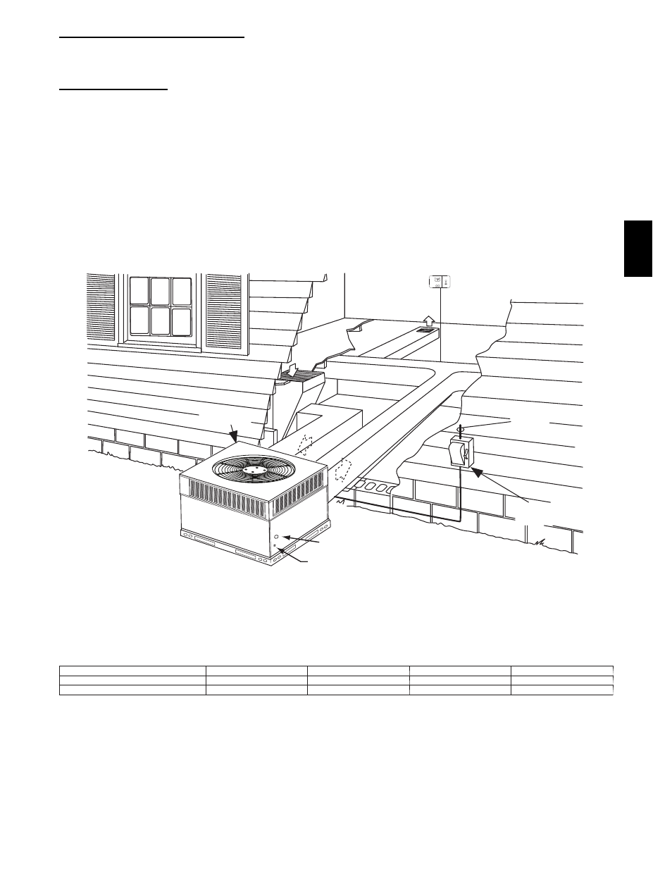
INDOOR
THERMOSTAT
DISCONNECT
PER NEC
FROM
POWER
SOURCE
RETURN
AIR
TOP COVER
POWER ENTRY
CONTROL ENTRY
A09098
Fig. 11 -- Typical Installation
Table 2 – Minimum Airflow for Reliable Electric Heater Operation (CFM)
SIZE
50JZ--A24
50JZ--A30
50JZ--A36
50JZ--A48
AIRFLOW (CFM)
800
1000
1200
1600
AIRFLOW (L/s)
378
472
567
756
50J
Z
--
A