Step 3 — outdoor fan, Step 4 — electrical controls and wiring, Step 5 — refrigerant circuit – Carrier 50JZ-A User Manual
Page 19: Step 6 — indoor airflow, Step 7 — metering device -- piston, Step 8 — pressure switches, Step 9 — loss of charge switch
19
Step 2 — Outdoor Coil, Indoor Coil, and
Condensate Drain Pan
Inspect the condenser coil, evaporator coil, and condensate drain
pan at least once each year.
The coils are easily cleaned when dry; therefore, inspect and clean
the coils either before or after each cooling season. Remove all
obstructions, including weeds and shrubs, that interfere with the
airflow through the condenser coil.
Straighten bent fins with a fin comb. If coated with dirt or lint,
clean the coils with a vacuum cleaner, using the soft brush
attachment. Be careful not to bend the fins. If coated with oil or
grease, clean the coils with a mild detergent--and--water solution.
Rinse coils with clear water, using a garden hose. Be careful not to
splash water on motors, insulation, wiring, or air filter(s). For best
results, spray condenser coil fins from inside to outside the unit. On
units with an outer and inner condenser coil, be sure to clean
between the coils. Be sure to flush all dirt and debris from the unit
base.
Inspect the drain pan and condensate drain line when inspecting
the coils. Clean the drain pan and condensate drain by removing all
foreign matter from the pan. Flush the pan and drain trough with
clear water. Do not splash water on the insulation, motor, wiring, or
air filter(s). If the drain tube is restricted, clear it with a plumbers
snake or similar probe device.
Step 3 — Outdoor Fan
Keep the condenser fan free from all obstructions to ensure
proper cooling operation. Never place articles on top of the
unit. Damage to unit may result.
1. Remove 6 screws holding outdoor grille and motor to top
cover.
2. Turn motor/grille assembly upside down on top cover to
expose fan blade.
3. Inspect the fan blades for cracks or bends.
4. If fan needs to be removed, loosen setscrew and slide fan off
motor shaft.
5. When replacing fan blade, position blade back to same posi-
tion as before.
6. Ensure that setscrew engages the flat area on the motor shaft
when tightening.
7. Replace grille.
Step 4 — Electrical Controls and Wiring
Inspect and check the electrical controls and wiring annually. Be
sure to turn off the electrical power to the unit.
Remove access panels (see Fig. 18) to locate all the electrical
controls and wiring. Check all electrical connections for tightness.
Tighten all screw connections. If any discolored or burned
connections are noticed, disassemble the connection, clean all the
parts, restrip the wire end and reassemble the connection properly
and securely.
After inspecting the electrical controls and wiring, replace all the
panels. Start the unit, and observe at least one complete cooling
cycle to ensure proper operation. If discrepancies are observed in
operating cycle, or if a suspected malfunction has occurred, check
each
electrical
component
with
the
proper
electrical
instrumentation. Refer to the unit wiring label when making these
checkouts.
Step 5 — Refrigerant Circuit
Inspect all refrigerant tubing connections and the unit base for oil
accumulation annually. Detecting oil generally indicates a
refrigerant leak.
If oil is detected or if low performance is suspected, leak--test all
refrigerant tubing using an electronic leak detector, or liquid--soap
solution. If a refrigerant leak is detected, refer to Check for
Refrigerant Leaks section.
If no refrigerant leaks are found and low performance is suspected,
refer to Checking and Adjusting Refrigerant Charge section.
Step 6 — Indoor Airflow
The heating and/or cooling airflow does not require checking
unless improper performance is suspected. If a problem exists, be
sure that all supply--air and return--air grilles are open and free
from obstructions, and that the air filter is clean. When necessary,
refer to Indoor Airflow and Airflow Adjustments section to check
the system airflow.
Step 7 — Metering Device -- Piston
This unit uses a fixed orifice metering device for both cooling and
heating modes.
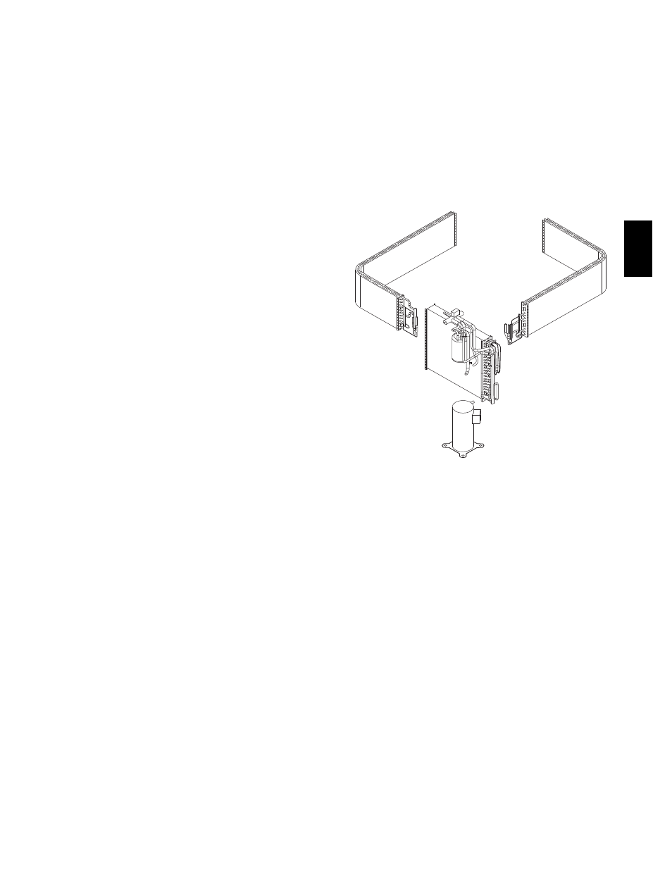
C99097
Fig. 19 -- Refrigerant Circuit
Step 8 — Pressure Switches
Pressure switches are protective devices wired into control circuit
(low voltage). They shut off compressor if abnormally high or low
pressures are present in the refrigeration circuit. These pressure
switches are specifically designed to operate with Puron (R--410A)
systems. R--22 pressure switches must not be used as replacements
for the Puron (R--410A) system.
Step 9 — Loss of Charge Switch
This switch is located on the liquid line and protects against low
suction pressures caused by such events as loss of charge, low
airflow across indoor coil, dirty filters, etc. It opens on a pressure
drop at about 20 psig (138 kPa). If system pressure is above this,
switch should be closed. To check switch:
1. Turn off all power to unit.
2. Disconnect leads on switch.
3. Apply ohm meter leads across switch. You should have
continuity on a good switch.
NOTE:
Because these switches are attached to refrigeration
system under pressure, it is not advisable to remove this device for
troubleshooting unless you are reasonably certain that a problem
exists. If switch must be removed, remove and recover all system
charge so that pressure gauges read 0 psi. Never open system
without breaking vacuum with dry nitrogen.
50J
Z
--
A